I recently had an opportunity to solder up some of my custom PCBs. It wasn’t a roaring success as I made a bit of a boo-boo with the LDO.
Regardless, I managed to flash some code onto my board and got it all running!
Aside from the need to fix my PCB design, I needed to seriously lower the power consumption of my board. It was averaging 4mA, which meant it would chew through batteries.
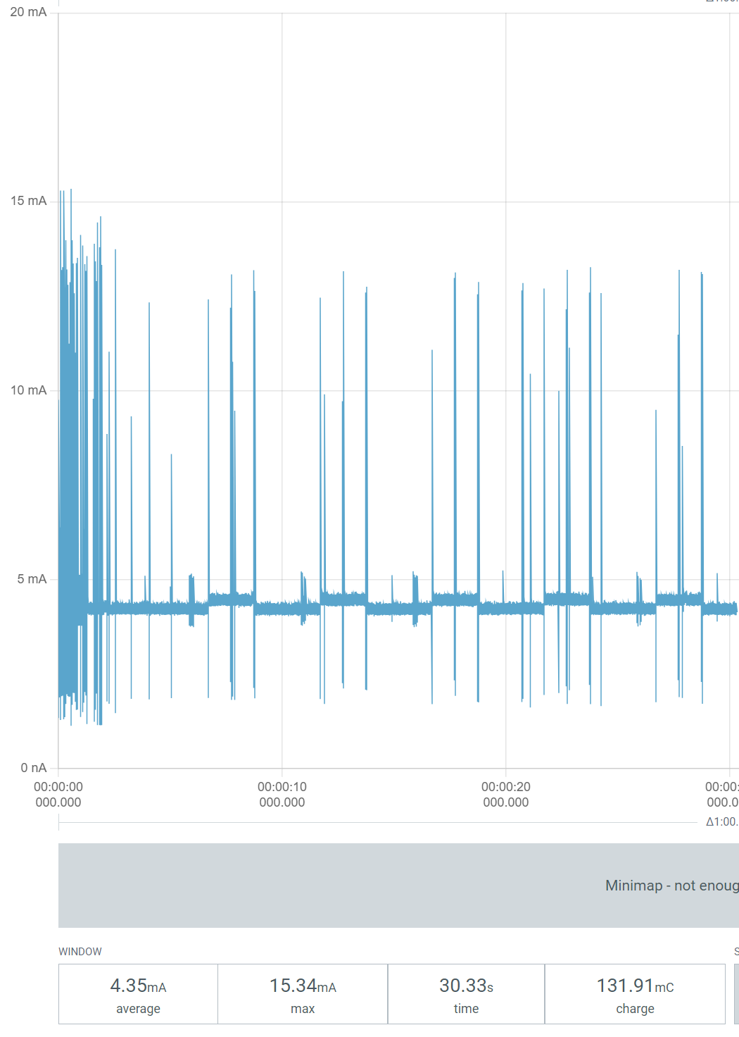
I didn’t even have any additional components to blame, since I was powering the module directly! My experience with the nRF52840 taught me a lot about how to reduce power for Zigbee. However, this project was a different “Matter”. Because I’m using the Matter protocol. Get it?
Switching my device to ICD
It was time to revisit my code and ensure it was running the hardware as *lean* as possible. This would involve enabling ICD (Intermittent Connected Device). This is a special low power mode for Matter, which allows the CPU to sleep for long periods of time. This helps conserve power.
I decided to start with my Nordic nRF54L15 DevKit rather than my custom board. It’s easier to work on the dev kit as I can flash directly. Measuring power consumption is also easier as there are dedicated headers.
First step was building it for the development kit in release mode. I chose to go back to the original overlay, rather than use the “internal” configuration. I wanted to see what the baseline consumption looked like.
west build -b nrf54l15dk/nrf54l15/cpuapp -p -- -DCONF_FILE=prj_release.conf
And that failed to compile. FML. Embedded programming is hard work!
matter/common/src/app/task_executor.h:43: undefined reference to `__device_dts_ord_10'
My bad. I had commented out the external flash in the .overlay file.😟I need a better way to differentiate between the Nordic DevKit, the MinewSemi devkit and my custom board….
Unfortunately, while the code compiled after fixing the overlay, it just didn’t run after flashing it.
So I went back to the Blinky sample. Story of my life. After compiling this, it flashed just fine over the J-Link remote server. That meant the programming remotely was working.
So, after a lot of messing around, I realised I was using the wrong GPIOs for the nRF54L15 DevKit. I found the right values here: https://docs.nordicsemi.com/bundle/ug_nrf54l15_dk/page/UG/nRF54L15_DK/hw_desription/buttons_leds.html
I was using GPIO pins that didn’t exist, which was causing the code to crash at runtime.
I put in the right values and bingo. I was then able to compile, flash and commission the device using iOS Home!
Identify yourself!
Whilst I was messing with code, I figured I should knock off another outstanding dev task: Identify support.
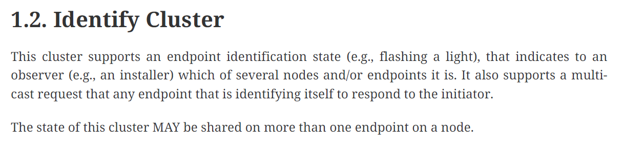
Matter has the ability, like Zigbee, to ask a device to identify itself. This is helpful when you have lots of similar devices, like downlights. You can ask the light to identify itself. This will usually take the form of a few flashes.
For my sensor, I want to blink the LED a few times. The Nordic Light Bulb sample supports this behaviour, so I just copied it.
First step was turning on the Identify cluster in the .zap file. This was done with the ZAP tool, launched via west
west zap-gui
I switched on the Server under the Root Endpoint.
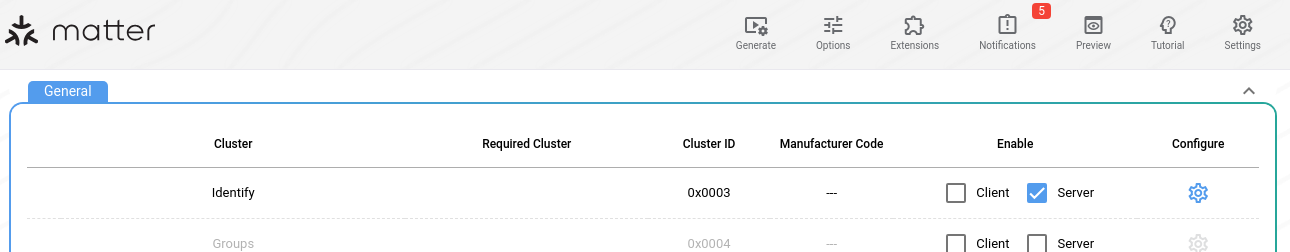
Under the cluster, I set the IdentifyType to 0x02, which represents VisibileIndicator

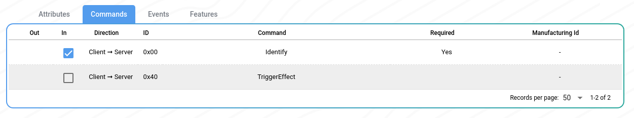
I also checked the Identify command was switched on. This command is mandatory, so it was enabled by default.
After saving the file, I then regenerated the ZAP files
west zap-generate
Once generated, I added some code to my app_task to support the new cluster.
First, I added the header to app_task.cpp
#include <app/clusters/identify-server/identify-server.h>
Next, I added a pointer to the Identify cluster in app_task.h
struct Identify;
Then I added two functions to the class definition
static void IdentifyStartHandler(Identify *);static void IdentifyStopHandler(Identify *);
In app_task.cpp, I then instantiated an instance of Identify cluster.
Identify sIdentify = {kLightEndpointId, AppTask::IdentifyStartHandler, AppTask::IdentifyStopHandler, Clusters::Identify::IdentifyTypeEnum::kVisibleIndicator};
Finally, I implemented the two functions. One to start the blinking and one to stop it.
void AppTask::IdentifyStartHandler(Identify *){ k_timer_stop(&sIndicatorTimer); k_timer_start(&sIndicatorTimer, K_MSEC(500), K_MSEC(500));}void AppTask::IdentifyStopHandler(Identify *){ k_timer_stop(&sIndicatorTimer); gpio_pin_set_dt(&indicator_led, 0);}
This worked as expected when I triggered Identify from iOS Home when commissioning. After adding the DK to my Aqara app, I was able to trigger it from there too.
Back to Power
With that little diversion finished, I returned to lowering power. I started by adding the basics for enabling the ICD mode. I also opted for something called LIT, which is Long Interval Time, a variant of the ICD.
CONFIG_PM_DEVICE=yCONFIG_OPENTHREAD_MTD=yCONFIG_OPENTHREAD_NORDIC_LIBRARY_MTD=yCONFIG_CHIP_ENABLE_ICD_SUPPORT=yCONFIG_CHIP_ICD_LIT_SUPPORT=y
Flashing this on had a pretty profound impact on power consumption. Remember, it was averaging ~4mA before these changes…
A 1-minute rolling average of 375µA was a good start.
Next, I added this setting: CONFIG_RAM_POWER_DOWN_LIBRARY. This had no real impact on the power consumption, which was fine.
Next up, I switched off the uart20 peripheral
&uart20 { status = "disabled";};
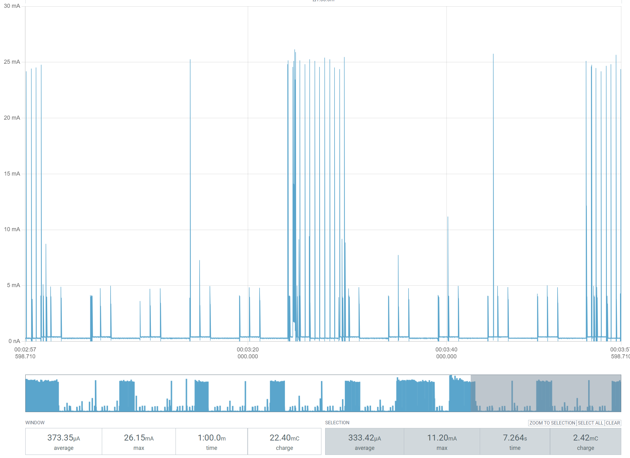
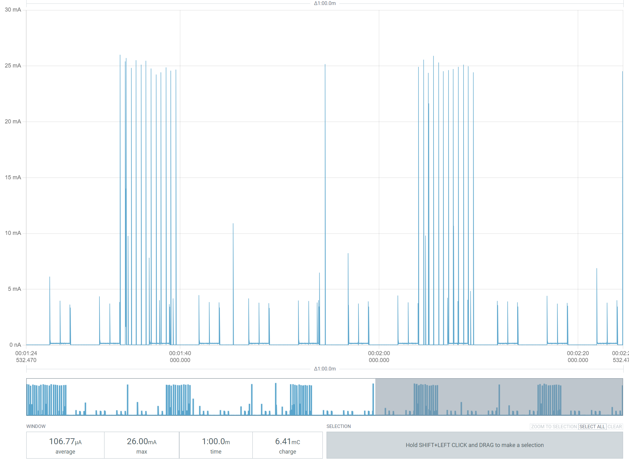
This had a nice effect, taking consumption down to a little over 100µA.
Good, but I think there is room for improvement. During the periods between readings, the chip should be pretty quiet. Zooming in shows it’s not.
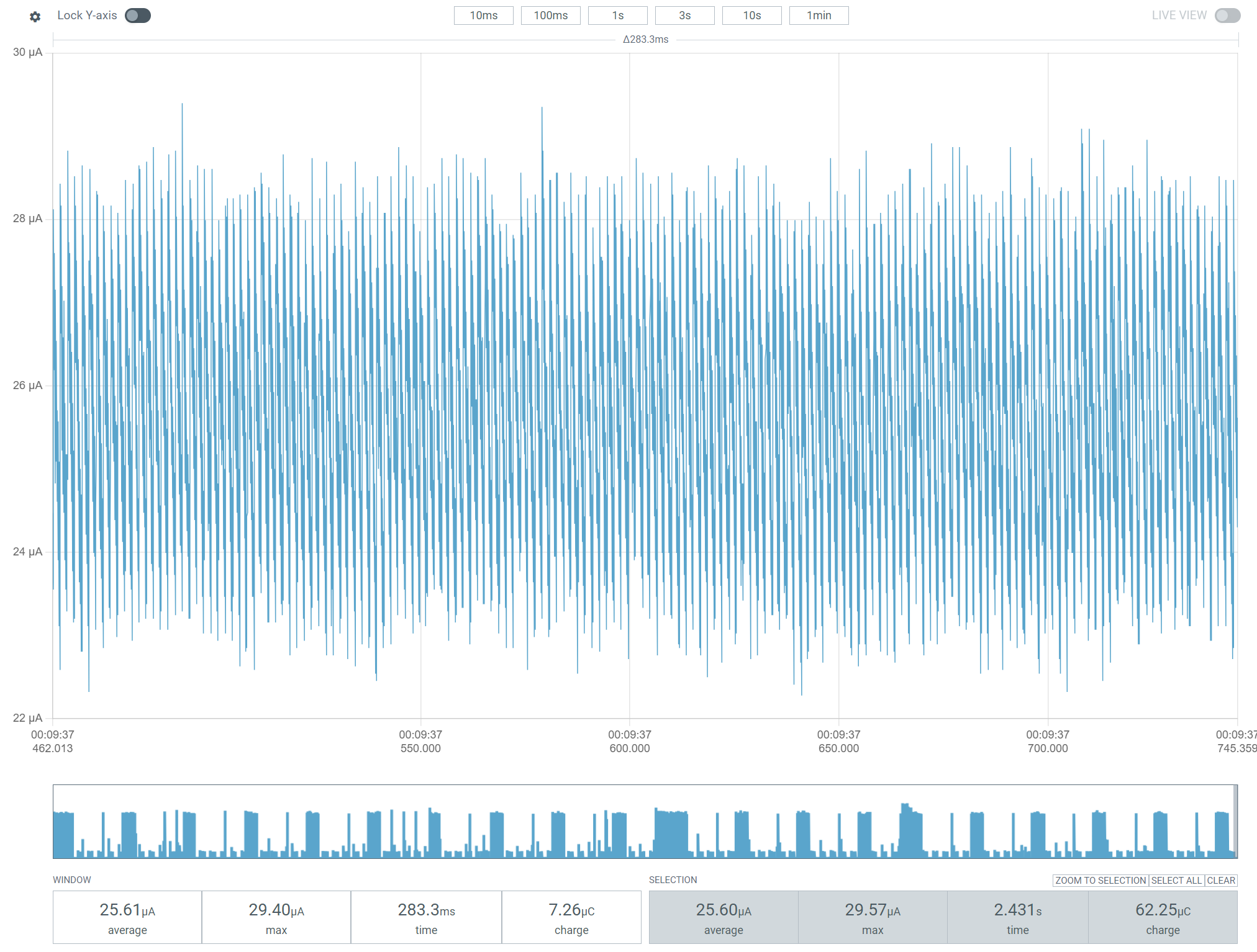
The chip should be pretty much asleep here, drawing only a few µA. I performed a build using the prj_release.conf, hoping that might help, but it didn’t.
At this point, I wondered if the external flash might bw the cause of the power consumption? The documentation indicated it wouldn’t – https://docs.nordicsemi.com/bundle/ug_nrf54l15_dk/page/UG/nRF54L15_DK/hw_desription/external_memory.html
Could this be the CPU *talking* to the external flash? I decided to try the “Internal” overlay, which turned off the external flash entirely.
This didn’t have much effect. The “quiet” period still used about 25µA.
I posted a question to Nordict (https://devzone.nordicsemi.com/f/nordic-q-a/125715/identifying-power-draw-during-sleep-period-of-matter-icd-device-on-nrf54l15-dk) and parked the problem.
Reading the sensors
As you’ve no doubt spotted on the power charts, there are 2 second periods that match my ADC code. As I wanted to let the voltage settle, I was leaving the power pins energised for whole second each.
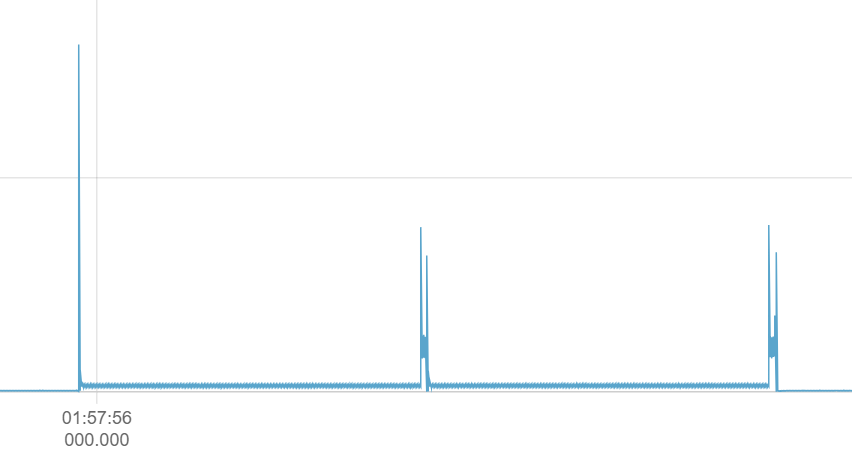
I reduced the “on” time of the divider power pins to 50ms and I added a 50ms gap between readings. I also increased the time between readings to 30 seconds.
This had a sizable impact, taking the average down to under 50µA.

A 1,000mAh battery would run for almost three years at that power consumption!
Trying my custom board
Whilst I waited for a reply from Nordic, I moved to running this low power code on my custom PCB. In theory the MinewSemi module should draw the same amount of power. The results were excellent!
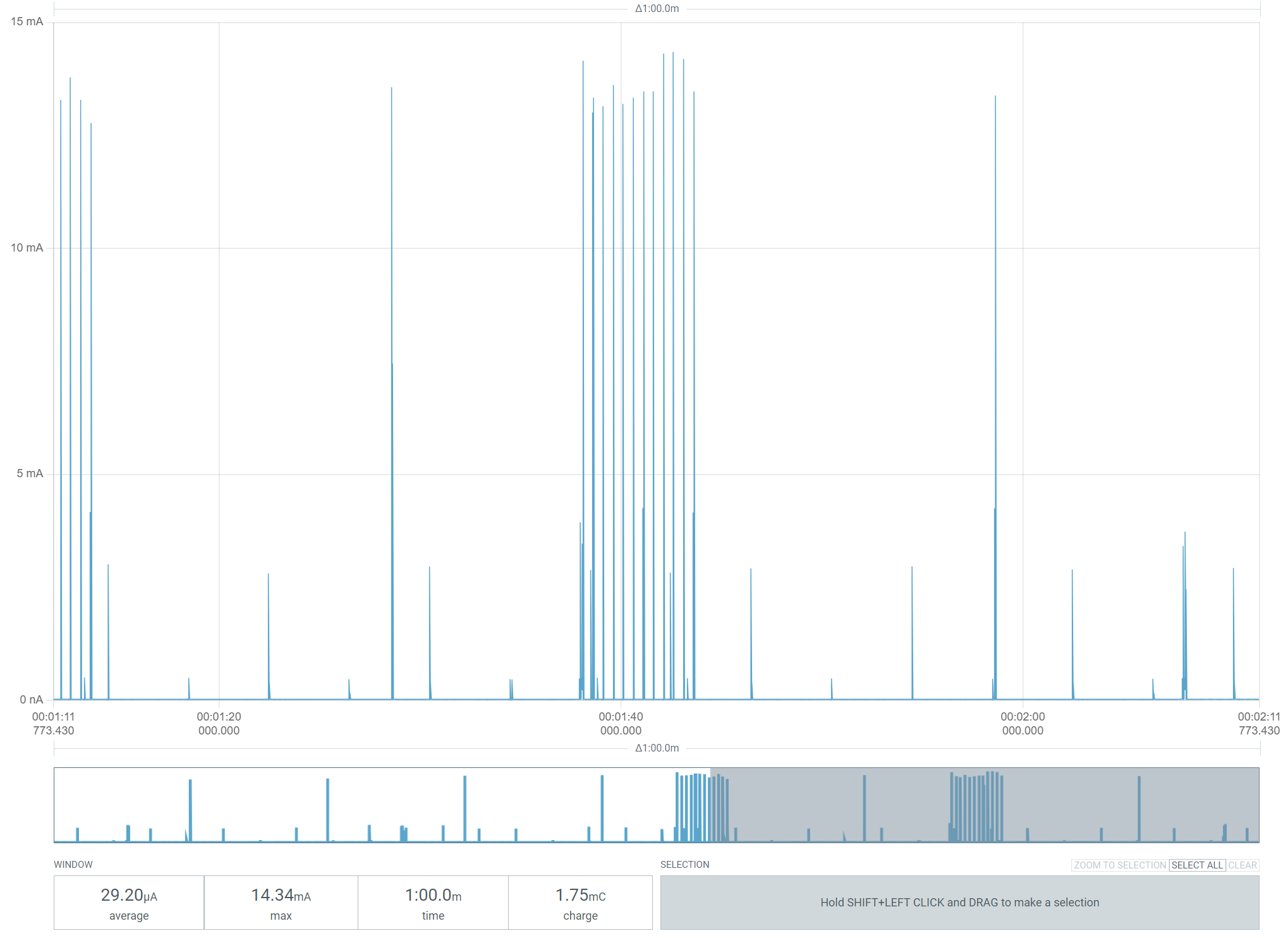
The draw was very low. This does exclude the quiescent current from the LDO (as it’s bypassed), but 30µA is still brilliant.
Next Steps
This exercise has gone better than I expected. It’s not matching the low power I achieve with the nRF52840, but that’s not the end of the world. I’ll wait for a response from Nordic on my question and fingers crossed that will give me some pointers.
In the meantime, I’ve got two working sensors, so I’ll get them into position on two radiators.
I’ve ordered updated PCBs from Aisler, with corrections for the LDO, so I hope to get them before December. I have one more MinewSemi module, so I’ll need more of those once I’m happy the PCB is okay.
Time to turn my attention to the management software now. No point in having lots of sensors, if I can’t do anything with the data 🙂
Did you like reading this post?
If you found this blog post useful and want to say thanks, you’re welcome to buy me a coffee. Better yet, why not subscribe to my Patreon so I can continue making tinkering and sharing.
Be sure to check out my YouTube Channel too – https://youtube.com/tomasmcguinness
Thanks, Tom!

Leave a comment