
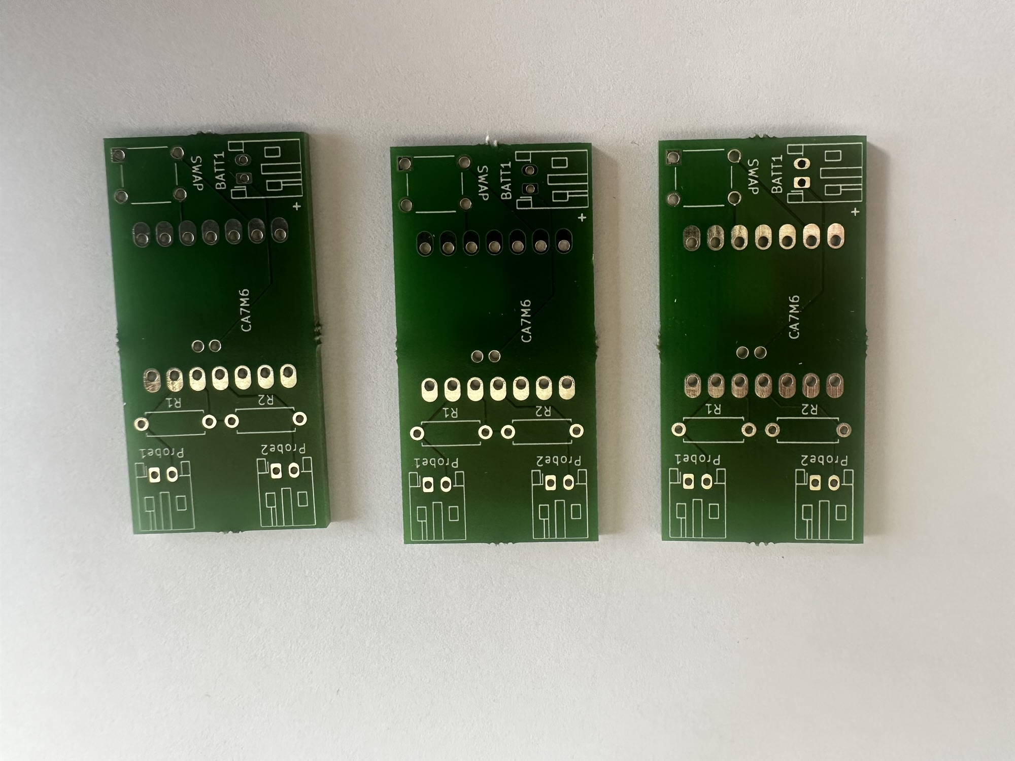
I received the 3rd revision of my Zigbee PCBs from Aisler today and unfortunately, there are still small issues.
Revision 3 of the these boards saw me switch from SMD to through-hole. Working with surface mounted components seemed like a great idea, but without the proper tools, I wasn’t equipped to do a good job.
The lack of a hot air soldering station or reflow oven meant that removing any of the XIAO boards was incredibly difficult. I have about 7 boards where I cannot reuse the board as I’m unable to remove them from their PCBS.
My goal with moving to through hole was to use header sockets, so that the XIAO boards would be easy to install and remove.
My Inspiration
My inspiration for this was the XIAO Expansion Board. This board uses header sockets and pogo pins. However, instead of the pogo pins touching the J-Link pads, they would connect with the battery pads.

The pogo pins were easy to find, but they were very expensive to buy. Where I really struggled, was finding the right sort of header sockets.
The ones I had were way too tall at 8.5mm, so whilst the board would fit, the pins weren’t tall enough to each the battery terminals.

This is what it should roughly look like

I ordered two different types of header sockets from digikey and both were *wrong*. I just wasn’t reading the datasheets accurately enough. One was the right height, but the header pins didn’t fit and the other one was too tall.
I have since found some from Mouser, which are the right length and height. I hope! They’ll arrive in the next few days.
Pogo Pins
Whilst sourcing the pogo pins was easy, I had a problem with the PCB. You see, the hole I was using for the battery terminals in Revision 2 was actually 1.8mm in diameter. I switched from an oval pad back to a circular one, but never adjusted the diameter of the hole.
The hole is far too wide for the foot of the pogo pins.
This means that instead of sitting upright, the pins simple flop to the side. This isn’t a massive issue, since ultimately the solder will hole them in place, but it’s not ideal.

Next Steps
I’m waiting on the new socket headers from Mouser and once they arrive, I’ll try to put together a complete sensor!
I hope this idea of using the pogo pins and socket works!!

Leave a comment