
In this post, I’m going to attempt to get a rotary encoder working with an ESP32-C6. The goal is to create a Matter Light Switch, with the rotation providing dimming control.
I’ll be using an ESP32-C6-DEV-KIT-N8 from WaveShare and a HW-040 Rotary Encoder.
I’m going to build upon my existing code, so if you find I’ve jumped ahead, read these posts:
- https://tomasmcguinness.com/2025/03/08/the-esp-matter-light-switch-example-and-ios/
- https://tomasmcguinness.com/2025/03/12/adding-dimming-to-the-matter-light-switch/
- https://tomasmcguinness.com/2025/03/18/adding-dimming-to-the-matter-light-switch-pt2/
The HW-040 is rated for 5V, but I’m hoping since it’s mostly mechanical, it will work with 3.3v from the ESP32.
The code for this project is available at https://github.com/tomasmcguinness/matter-esp32-rotary-dimmer-switch
Starting small
To start me off, I’m going to try and get the push operation working. This should be a case of monitoring a GPIO for a High. The rotary encoder is more complicated, so I’ll tackle that next!
I will be using the espressif-iot button component. This gets added on top of the GPIO and it offers power saving in addition to click, double click, etc.

I’m going to choose GPIO10 as the input for the switch. This is because it’s also the 10th GPIO on the left. Makes it easier to find.
The HW-040 has an SW button output and this represents the push operation. It will be at 3.3V until the button is pushed.

I then connected this terminal to GPIO 10.
The code in the app_driver_switch_init method looks like this
button_config_t config;
memset(&config, 0, sizeof(button_config_t));
config.type = BUTTON_TYPE_GPIO;
config.gpio_button_config.gpio_num = GPIO_NUM_10;
config.gpio_button_config.active_level = 1;
button_handle_t handle = iot_button_create(&config);
ESP_ERROR_CHECK(iot_button_register_cb(handle, BUTTON_SINGLE_CLICK, app_driver_button_single_click_cb, NULL));
I setup a button_config_t, configure it with GPIO_NUM_10 and set its active_level to 1. I then add a callback for the BUTTON_SINGLE_CLICK.
The callback just contains a log statement for now.
static void app_driver_button_single_click_cb(void *arg, void *data)
{
    ESP_LOGI(TAG, "Single Click");
}
After flashing the code, clicking the button shows this in the monitor
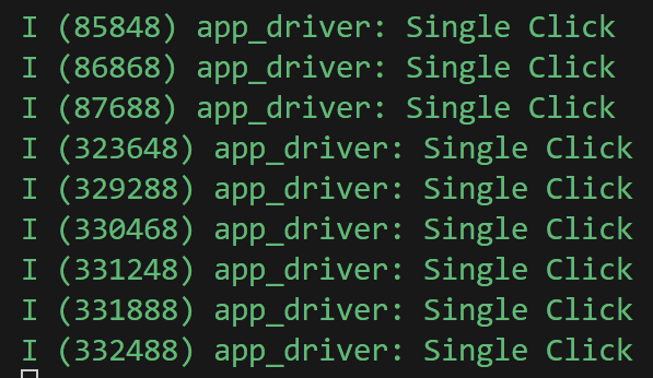
It worked, but rapid clicking of the button didn’t always register. The iot-button library requires the button be pressed for a minimum time to be considered a SINGLE_CLICK. My HW-040 is generating too short a pulse. To fix this, I switched to BUTTON_PRESS_DOWN. This means the callback will be invoked as soon as the button is clicked.
ESP_ERROR_CHECK(iot_button_register_cb(handle, BUTTON_PRESS_DOWN, app_driver_button_single_click_cb, NULL));Now, now matter how quickly I clicked, the even registered.
Getting Complicated!
The rotation part seems a lot more complicated.
The site esp32io.com contains loads of useful ESP32 stuff and they have a post on rotary encoders.
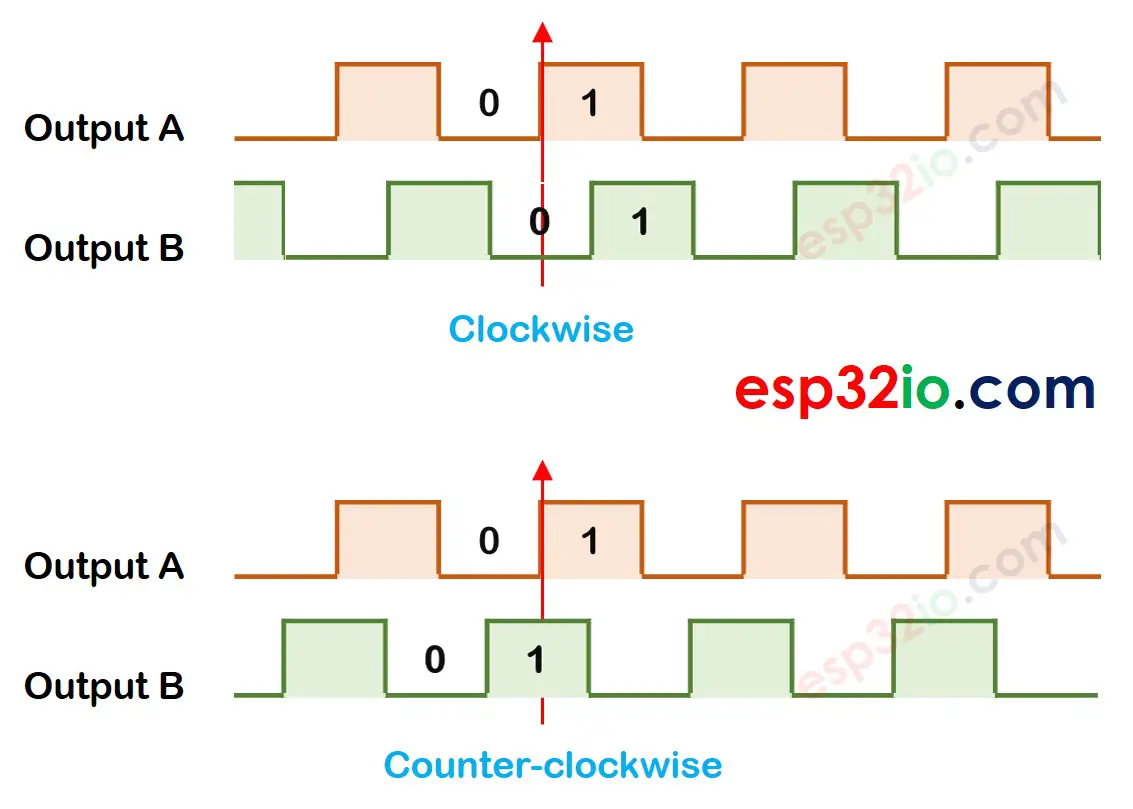
You can read the full blog post here. https://esp32io.com/tutorials/esp32-rotary-encoder
In summary, it we receive a 1 on Output A and Output B is 0, then we’re going clockwise. If we receive a 1 on Output A and Output B is already at 1, then we’re moving counter clockwise.
Thankfully, it looks like the ESP32 SDK has a way to do this for you: The Pulse Counter. Using the peripheral example, I added the necessary code.
This involved setting up the pcnt_unit
ESP_LOGI(TAG, "install pcnt unit");
pcnt_unit_config_t unit_config = {
    .high_limit = EXAMPLE_PCNT_HIGH_LIMIT,
    .low_limit = EXAMPLE_PCNT_LOW_LIMIT,
};
Once the rest of the example code is setup, there is a simple loop that checks a Queue.
int pulse_count = 0;
int event_count = 0;
while (1) {
if (xQueueReceive(queue, &event_count, pdMS_TO_TICKS(1000))) {
ESP_LOGI(TAG, "Watch point event, count: %d", event_count);
} else {
ESP_ERROR_CHECK(pcnt_unit_get_count(pcnt_unit, &pulse_count));
ESP_LOGI(TAG, "Pulse count: %d", pulse_count);
}
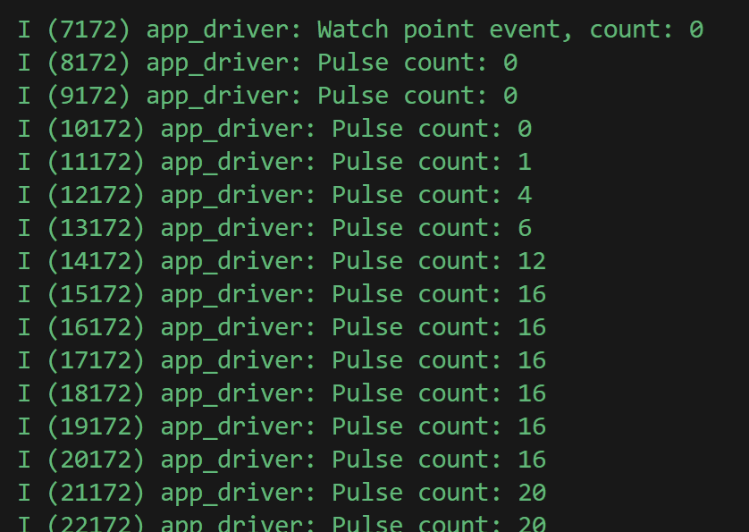
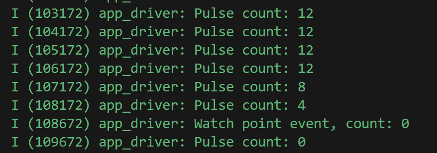
}There is something called WatchPoint in the sample code, but I’m going to ignore that for now. This loop runs continuously, waiting for a watch point event. If none is received, it will count the current number of pulses.
Firing that up and turning the knob results in this in the console.
Is Pulse Counting what I want?
At this point, I’m not really sure pulse counting is actually what I want. The pulse counter does exactly that, count pulses. I’m only interested in the turns, not the number of turns. Let’s try and make it work with Matter anyway.
The Dimmer in Matter uses a cluster called LevelControl. I cover this in detail in my post on adding dimming. Like my touch button, I’ll be using steps rather than absolute.
The first step is moving the while(1) into a task. I can’t have a blocking loop running as this will prevent the Matter code from running.
static void pulse_counter_monitor_task(void *arg) { }I start this after the pulse counter is setup.
xTaskCreate(pulse_counter_monitor_task, "pulse_counter_monitor_task", 4096, NULL, 10, NULL);The stack is quite large and that’s necessary because of the Matter API call.
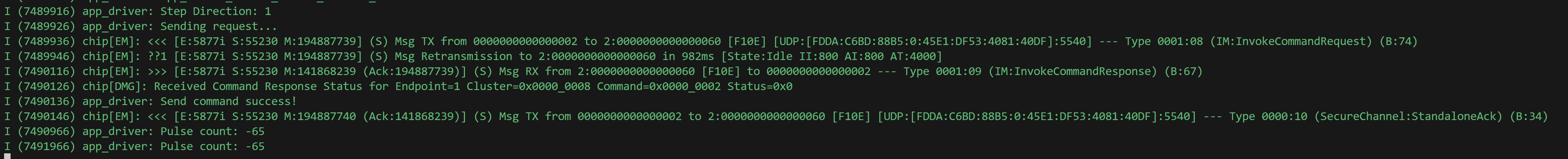
Inside the pulse_counter_monitor_task I raise a LevelControl Step command.
ESP_LOGI(TAG, "Pulse count: %d", pulse_count);
if (pulse_count != current_pulse_count)
{
    current_pulse_count = pulse_count;
    ESP_LOGI(TAG, "Sending Command");
    LevelControl::Commands::Step::Type stepCommand;
    stepCommand.stepMode = LevelControl::StepModeEnum::kUp;
    stepCommand.stepSize = 4;
    stepCommand.transitionTime.SetNonNull(0);
    stepCommand.optionsMask = static_cast<chip::BitMask<chip::app::Clusters::LevelControl::LevelControlOptions>>(0U);
    stepCommand.optionsOverride = static_cast<chip::BitMask<chip::app::Clusters::LevelControl::LevelControlOptions>>(0U);
    client::request_handle_t req_handle;
    req_handle.type = esp_matter::client::INVOKE_CMD;
    req_handle.command_path.mClusterId = LevelControl::Id;
    req_handle.command_path.mCommandId = LevelControl::Commands::Step::Id;
    req_handle.request_data = &stepCommand;
    lock::chip_stack_lock(portMAX_DELAY);
    client::cluster_update(dimmer_switch_endpoint_id, &req_handle);
    lock::chip_stack_unlock();
}
I maintain a current_pulse_count and only raise the command if the pulse count changes.
In this code, the direction is fixed to StepModeEnum::kUp and the stepSize is 4, which is a nice increment.
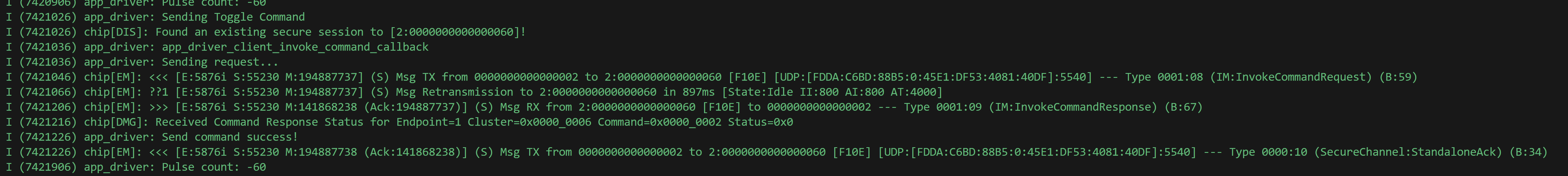
To make the click work, I added a Toggle command to the app_driver_button_single_click_cb method.
static void app_driver_button_single_click_cb(void *arg, void *data)
{
    ESP_LOGI(TAG, "Sending Toggle Command");
    client::request_handle_t req_handle;
    req_handle.type = esp_matter::client::INVOKE_CMD;
    req_handle.command_path.mClusterId = OnOff::Id;
    req_handle.command_path.mCommandId = OnOff::Commands::Toggle::Id;
    lock::chip_stack_lock(portMAX_DELAY);
    client::cluster_update(dimmer_switch_endpoint_id, &req_handle);
    lock::chip_stack_unlock();
}
Brighten and Darken
A good dimmer works in both directions. To crudely approximate this, I check the new pulse count against the previous and then send the appropriate direction.
int pulse_difference = pulse_count - current_pulse_count;
LevelControl::StepModeEnum step_direction = LevelControl::StepModeEnum::kUp;
ESP_LOGI(TAG, "Pulse Difference: %d", pulse_difference);
if(pulse_difference < 0)
{
    step_direction = LevelControl::StepModeEnum::kDown;
}
I also want to ensure that long spells of rotation are accurately reflected too. One small rotation results in a pulse count of four. If I turn it a lot, I get a bigger number (inside that one second timeout).
int stepSize = pulse_count / 4;
ESP_LOGI(TAG, "Sending Step Command");
LevelControl::Commands::Step::Type stepCommand;
stepCommand.stepMode = step_direction;
stepCommand.stepSize = stepSize;
This code will see how many rotations were made and then send an appropriate stepSize.
Connecting to a real bulb
With the code finished, it’s time to test. To do that, I’m going to connect my ESP32-C6 to a Nanoleaf Matter Bulb. As I need to Bind the light switch to the bulb, I will use the chip-tool. I’ve done this already and you can read about it in this post.
I start by pairing the bulb with the chip-tool. Since I’m using an ESP32-C6, it has WiFi, so I can configure it directly. This will command will pair the C6 and connect it to the WiFi.
chip-tool pairing ble-wifi 0x02 <SSID> <PASSWORD> 20202021 3840Next, I grant this node, 0x02, access to my Nanoleaf bulb 0x60. 84 is include in the subjects as I want to preserve access to my ESP32-H2 touch button.
chip-tool accesscontrol write acl '[{"privilege": 5, "authMode": 2, "subjects": [ 112233, 84, 2 ], "targets": null}]' 0x60 0x0Finally, I bind my dimmer to the OnOff and LevelControl clusters of the light.
chip-tool binding write binding '[{"node":96, "endpoint":1, "cluster":6},{"node":96, "endpoint":1, "cluster":8}]' 0x02 0x1Amazingly, this works first time! The OnOff sends a command and rotating the encoder sends a command too!
Whilst the dimming works, the code that *should* make larger steps is terrible. That’s an improvement to make!
Summary
That was an interesting dive into rotary encoders. I have lots of improvements to make to this code, but this is a solid start!
Next up will be improving the stepping code and maybe shortening the delay so it seems more responsive.
I also want to enable light-sleep across this code so I can hopefully run a device off a few batteries. I will also use Thread instead of WiFi (which the C6 supports too). I need to check the quiescent current of the HW-040, but I’m hoping it won’t be too high!
Did you like reading this post?
If you found this blog post useful and want to say thanks, you’re welcome to buy me a coffee. Better yet, why not subscribe to my Patreon so I can continue making tinkering and sharing.
Be sure to check out my YouTube Channel too – https://youtube.com/tomasmcguinness
Thanks, Tom!

Leave a comment