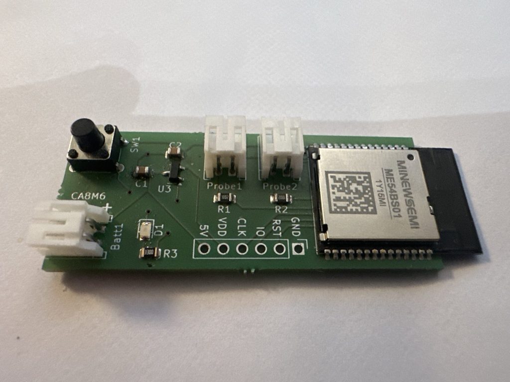
With my initial PCB designed and my code working on the Nordic DevKit, I turned attention to my ME54BE01 devkit. This board comes from MinewSemi and is designed to support their nRF54L15 modules.
Yes, I should have gotten my code working before getting PCBs made, but I figured it should be easy enough.
After getting the Blinky sample running on the MinewSemi DevKit, I started by flashing my custom firmware.
It flashed successfully and I hit the reset button.
I tried to pair the device using iOS home, but it couldn’t find it. This could only mean one thing – my code wasn’t running.
How to debug this?
I drew an absolute blank here.
.Net is my bread and butter, not micro-controllers. Each time I hit a problem, I have to figure it out from scratch.
The Blinky sample worked, so I was confident that the module was getting power and the code flashed correctly. My soldering is questionable, but the module was booting and running code.
I knew Zephyr had a debugger, so I ran this command
west debugThe debugger appeared to start and after a little reading, I tried the backtrace command.
Resetting target
(gdb)
(gdb) backtrace
#0  z_arm_reset () at /home/tomasmcguinness/ncs/v3.1.0/zephyr/arch/arm/core/cortex_m/reset.S:73
The z_arm_reset didn’t fill me with much hope. Checking Nordic DevZone, did yield this post:
https://devzone.nordicsemi.com/f/nordic-q-a/125219/nrf-connect-debugger-stuck-on-arm-reset-s/552555
The OP had a program stuck and the response was to check the configuration was correct for the module. As I’m moving from the Nordic DevKit to the MinewSemi one, this advice seemed sensible. I added the suggested configuration, aside from the CONFIG_BOARD_ENABLE_DCDC as this wasn’t recognised.
The backtrace command error changed
(gdb) backtrace
#0  0x00003cba in ?? ()
#1  0x00002030 in ?? ()
Backtrace stopped: previous frame identical to this frame (corrupt stack?)
Ah yes, a corrupt stack. Just wanted to I wanted to read.
What are the possible issues?
Blinky worked. I needed to keep that in mind.
There were, however, a lot of differences between the Blinky sample and my Dual Sensor Firmware code.
Thinking back to other issues I experienced with XIAO boards, I recalled external flash being a problem. The MS54BE01 Devkit didn’t have external flash, but my overlay & partition has it configured. For example, the pm_static_nrf54l15dk_nrf54l15_cpuapp.yml file has this:
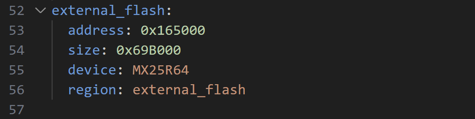
The corresponding overlay, shows this peripheral
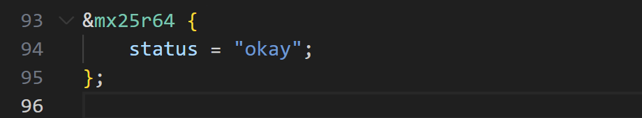
The MCU bootloader was configured to use the external_flash, so this appears to a likely candidate for my problem.
I started by commenting out all mention of secondary_boot and peripherals. That resulted in a compilation error.
/home/tomasmcguinness/ncs/v3.1.0/nrf/subsys/dfu/dfu_target/src/dfu_target_mcuboot.c:60:41: error: 'PM_MCUBOOT_SECONDARY_SIZE' undeclared here (not in a function); did you mean 'PM_MCUBOOT_SECONDARY_0_SIZE'?
   60 | #define PM_MCUBOOT_SECONDARY_0_SIZE     PM_MCUBOOT_SECONDARY_SIZE
I wondered if the secondary boot partition was needed just for OTA update? There is a standard approach of having two partitions on an MCU. One runs the current code and the other holds a different image. When an OTA image is written to the secondary partition, it just switches over.
If my Firmware was small enough, surely I could do it all on the internal flash? If this was going to be a deal breaker, I could also turn off OTA updates completely.
After more digging, I stumbled on this nice page:
It implies that external flash is needed, but also hints that it’s possible to do without:
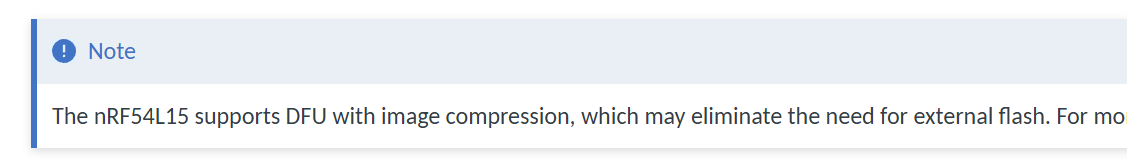
The page it points to, https://docs.nordicsemi.com/bundle/ncs-latest/page/nrf/app_dev/bootloaders_dfu/mcuboot_image_compression.html#mcuboot-image-compression, gave a sample partition file.
Giving that partition a go, I hit a different problem
Partition manager failed: Incorrect amount of gaps found in static configuration. There must be exactly one gap in the static configuration to support placing the dynamic partitions (such as 'app'). Gaps found (2):0x10800-0xcf000 0x165000-0x17d000 The most common solution to this problem is to fill the smallest of these gaps with statically defined partition(s) until there is only one gap left. Alternatively re-order the already defined static partitions so that only one gap remains.
Failed to partition region flash_primary, size of region: 1560576
Skipping OTA support altogether
I felt like I was going down a rabbit hole. One I didn’t need to bother with, since I didn’t care about OTA updates. Could I just ignore OTA updates?
Nordic answered it here – https://docs.nordicsemi.com/bundle/ncs-3.1.0/page/nrf/protocols/matter/end_product/bootloader.html
All Matter nodes are required to implement a firmware update mechanism that validates the authenticity of new firmware before executing it. To meet this requirement, Nordic Semiconductor recommends using MCUboot bootloader for installing a new firmware image.
Whilst it’s true that Device Firmware Updates (DFU) is a thing, for my little sensor, I didn’t care. I had no commercial aspirations for this product.
Unfortunately, turning it off didn’t seem to be an option!
Back to internal memory
After more reading about bootloaders, the Nodic documentation again referenced the use of just internal memory on the NRF54L15.
On this page, the reference memory layout shows an internal only memory section

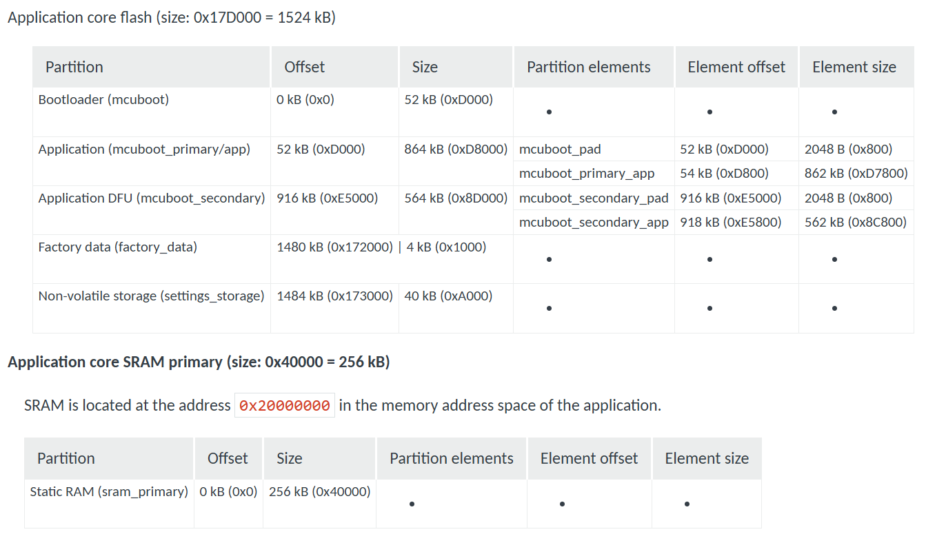
I checked the readme on the Matter Template sample and the penny dropped! There is a special section on using Internal Memory. Ah-ha!
My repo even included the damn file as I closed the Template sample! I just didn’t know what it meant.
I tried the build, using the -DFILE_SUFFIX=internal as directed.
west build -p -b nrf54l15dk/nrf54l15/cpuapp -- -DFILE_SUFFIX=internalI felt like it would fail due to the missing device tree settings, but tried anyway 🙂
It did fail.
I then created a new overlay and partition manager files for my module using the minewsemi suffix. I could compile and even flash, but the application still didn’t work.
Time to go back to basics again. I compiled the Matter Template sample using the Internal suffix and flashed it on. The little LED started blinking!!
My code didn’t work, but the Matter Template code *did*. Another step forward! It meant the Matter code with the internal configuration *could* work.
Now to find out what was wrong with my code. My approach, like always, was to strip everything back and add it back in, little by little.
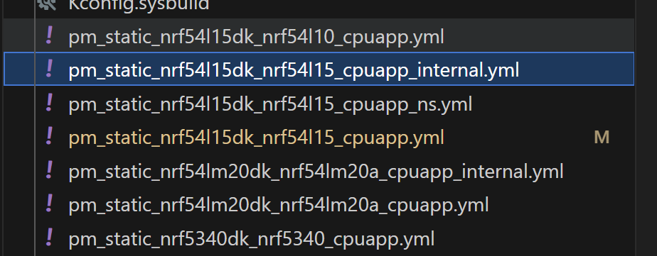
I commented out all my code and then noticed I’d failed to make a minewsemi version of the sysbuild file. This was quite crucial as it contained the compressed MCU boot settings. I cloned the existing sysbuild_internal.conf file and, bingo, I was in business!
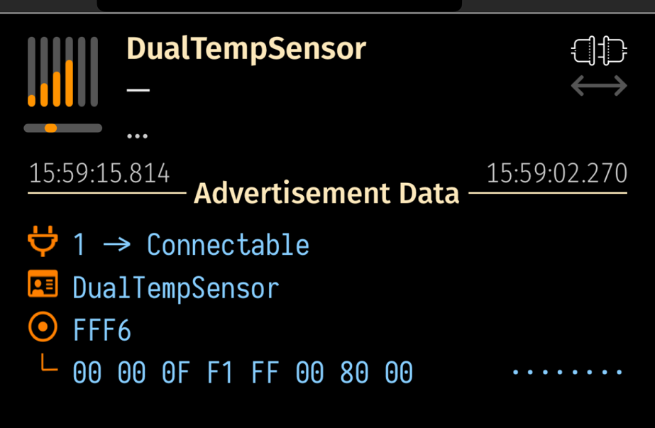
After flashing the skeleton project, I could see my Bluetooth device advertising itself.
I hastily restored all my code and tried again, using iOS Home
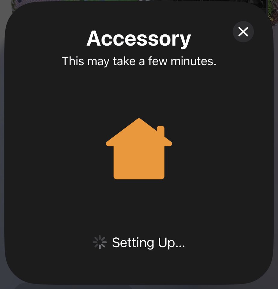
The device paired successfully, showing two temperature sensors.
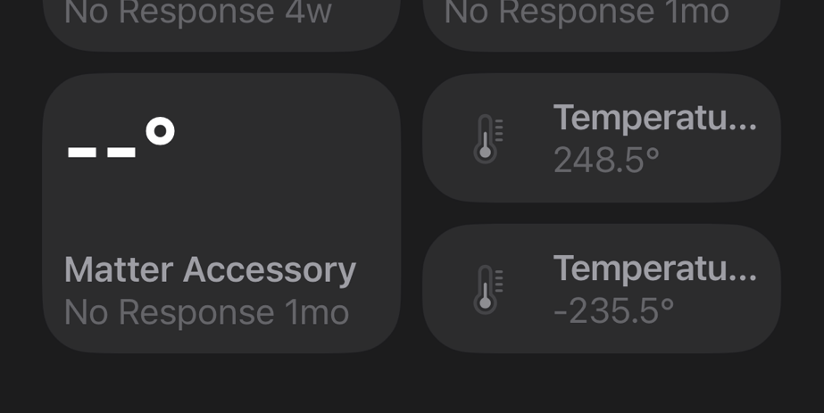
The readings were rubbish as the PINs were floating, but this was a huge first step with the MS54BS01 module.
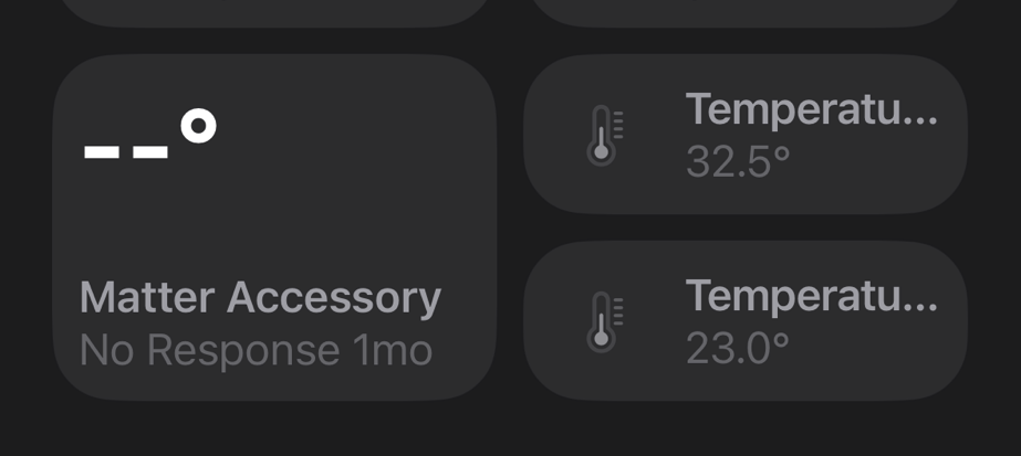
I finished up by hooking up my “probes”
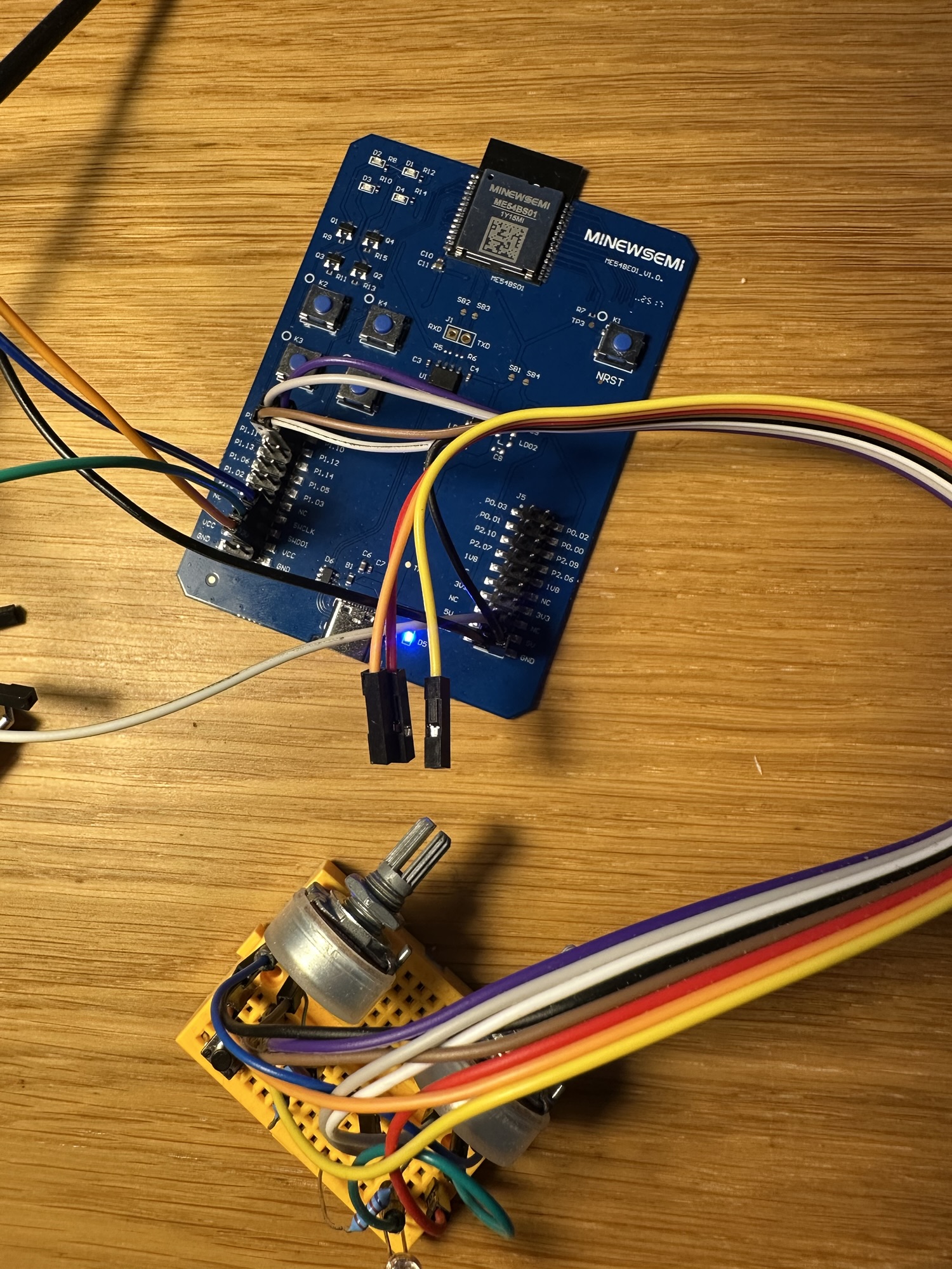
I was very happy to see some sensible values in iOS Home!
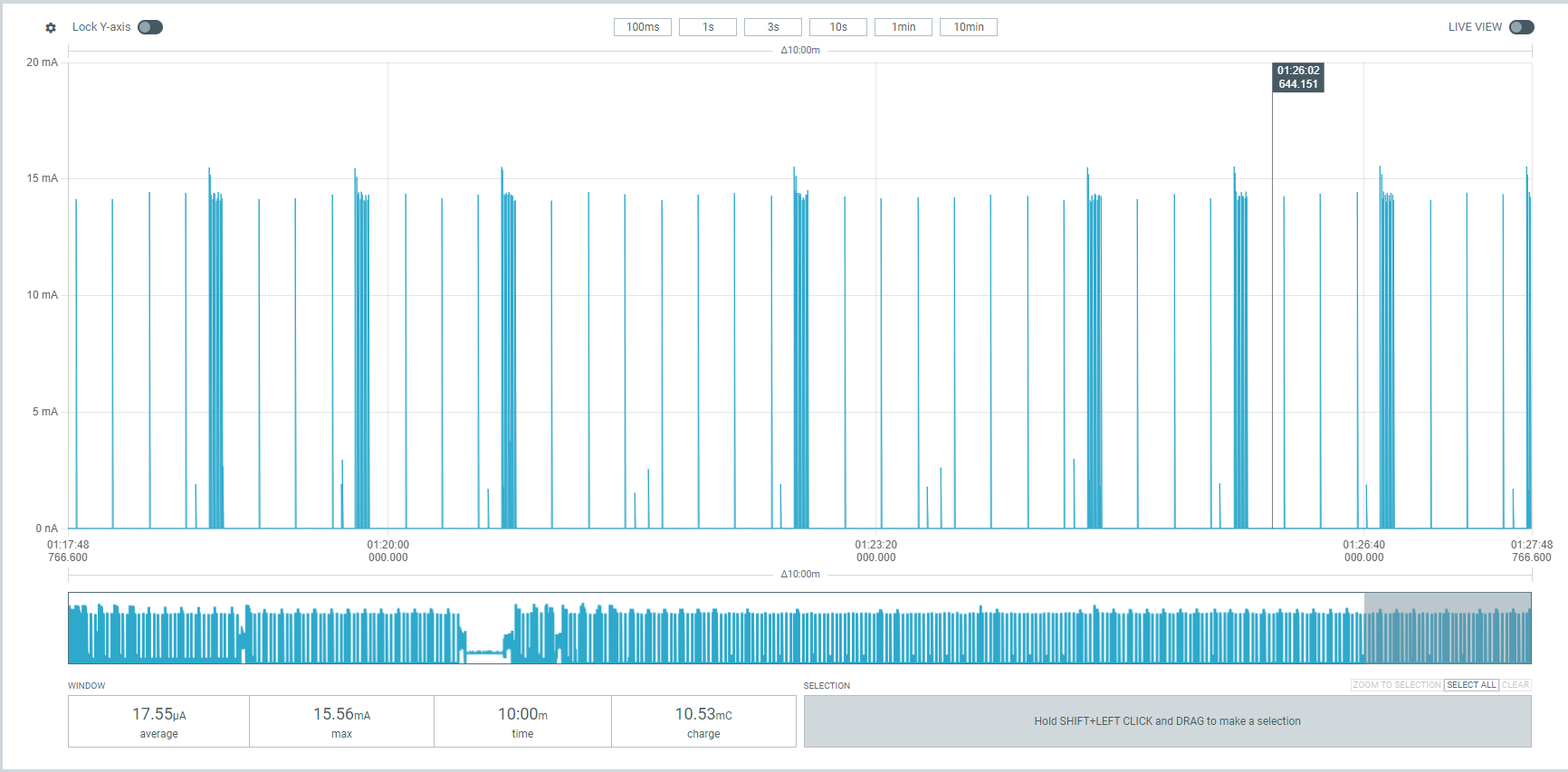
With it worked, I did a cheeky test of power consumption.

It’s pretty high at 5mA. Not helped by the fact one of the board’s LEDs turns on (must be connected to the power divider pin).
I need to configure my device as an ICD (Intermittent Connected Device) to improve battery life. I won’t get very far on a battery if I’m drawing 5mA!
Next Steps
I’m waiting for the next batch of custom PCBs to come from Aisler. Once I have these boards, I will set about soldering one. My first go at mounting tiny SMD resistors and capacitors. I hope I can simply flash the firmware and get a working sensor!
This has been an interesting process, and I have a better understanding of internal v external flash. As demonstrated, the nRF54L15 board can be configured to support OTA updates without external flash.
I really should give the OTA process a try at some point.
Let me get a working sensor first!
Did you like reading this post?
If you found this blog post useful and want to say thanks, you’re welcome to buy me a coffee. Better yet, why not subscribe to my Patreon so I can continue making tinkering and sharing.
Be sure to check out my YouTube Channel too – https://youtube.com/tomasmcguinness
Thanks, Tom!

Leave a comment