With the arrival of my latest Dual Temperature Sensor PCB, it was time to look at power consumption again.
In my last post on the subject in November 2025, I had managed to get consumption down to 30µ. This figure was higher than I wanted, especially as it didn’t include the hardware like the LDO. My benchmark was still the Zigbee version of this sensor, which run at 16µA.
For my power measurements, as always, I used my Nordic Power Profile Kit II.
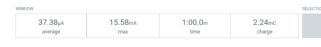
Reminding me where I was at
I connected the power profiler into the battery terminal of my custom board. This would sure all power was accounted for, not just the nRF54L15 module itself.
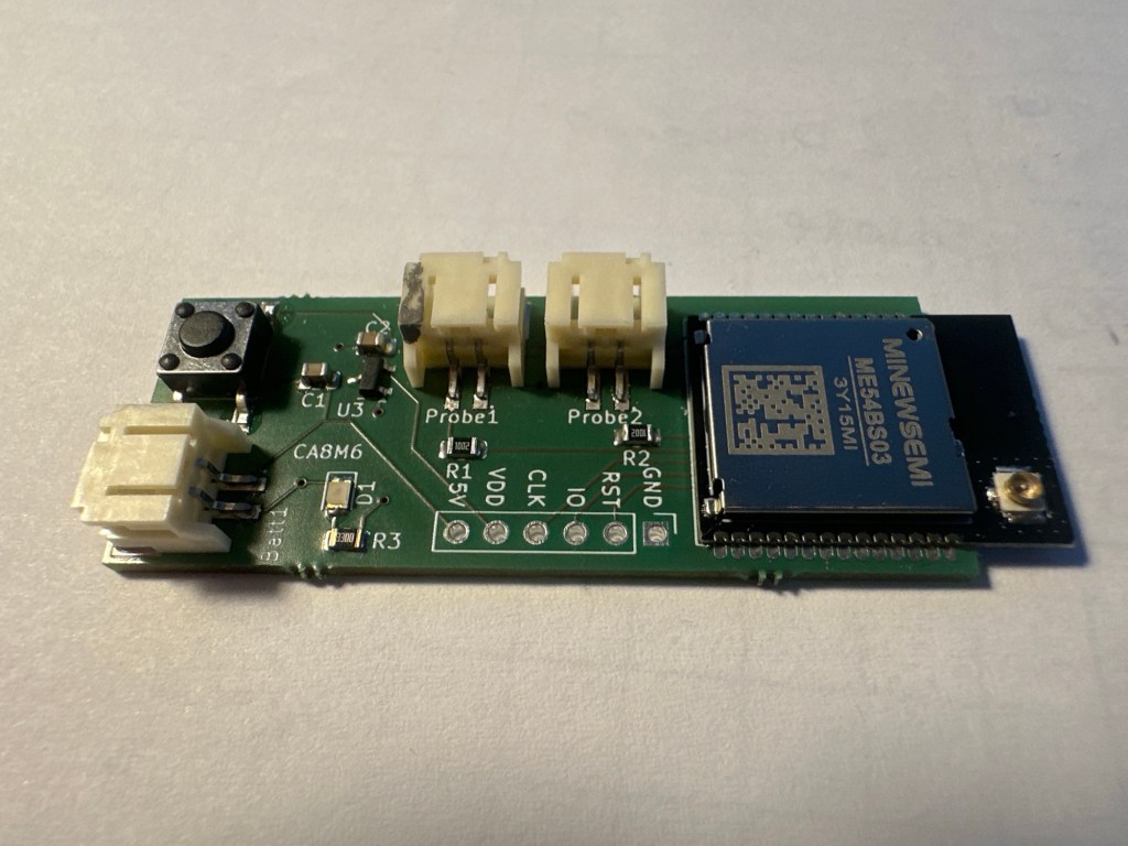
After commissioning, my consumption was a respectable 58µA. This was higher than my first go for two main reasons. First, I had increased the reading frequency. Second, this included *all* the hardware.
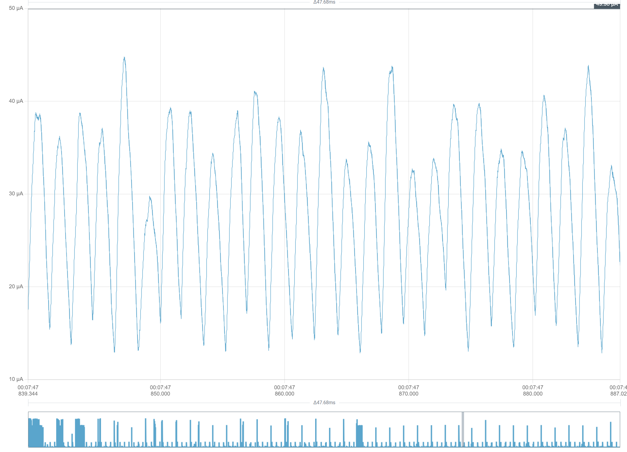
What troubled me was the noise of the sleep periods.
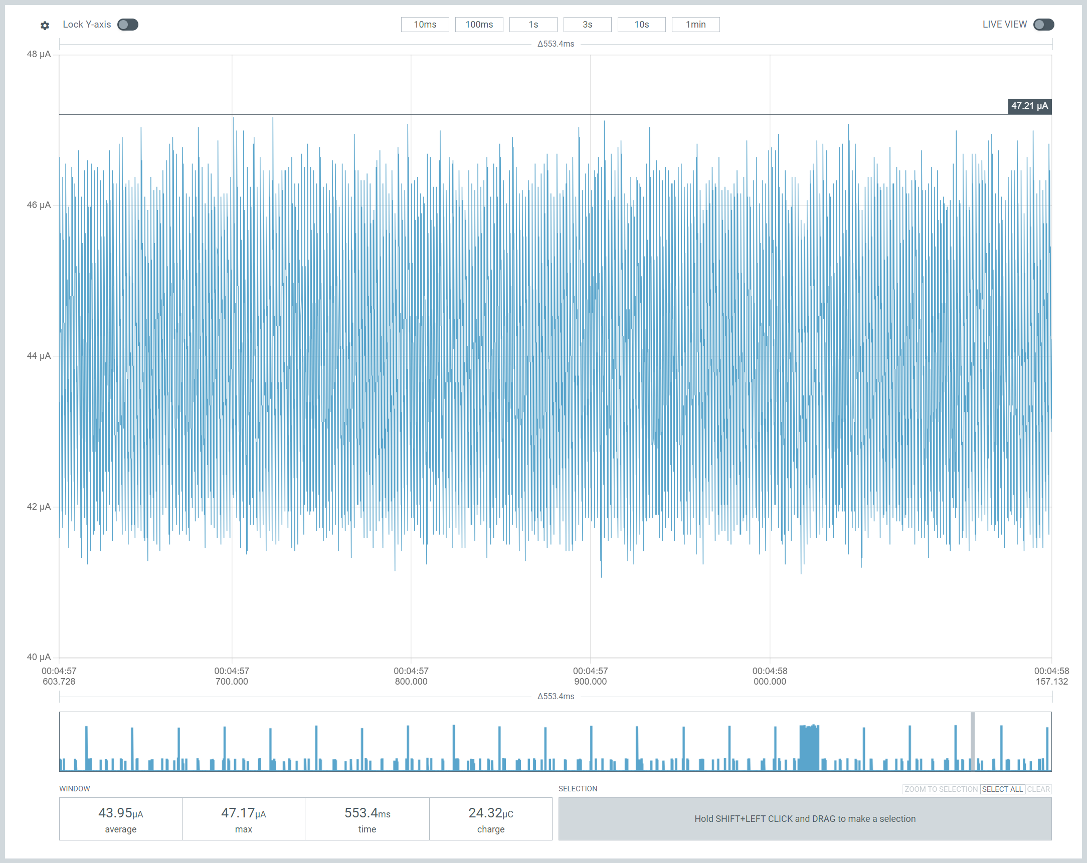
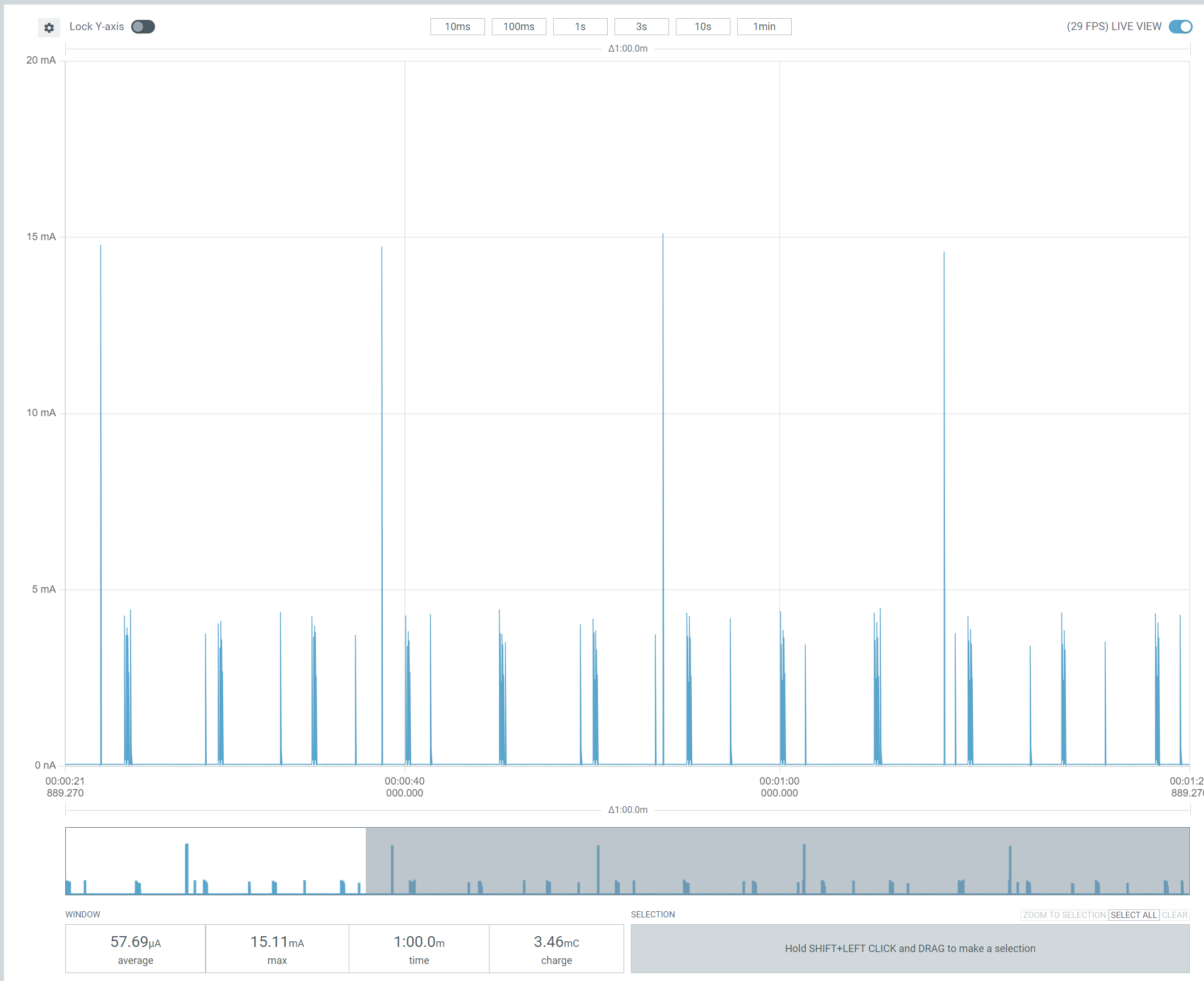
If we zoom in, this looks like something ticking along. The base consumption is also over 40µA.
According to Nordic, the idle current should only be 5 or 6µA. The LDO I’m using, MCP1700T-2202E/TT, has a quiescent current of around 2µA,. That meant it shouldn’t be consuming more than 10µA.
Back to basics
A phrase I use a lot 🙂
I needed to understand what my PCB did with minimal code. No Matter, no ADC, no ICD, just code that puts the chip to sleep.
System Off
I installed the Zephyr System Off sample onto my custom PCB and the results were amazing.
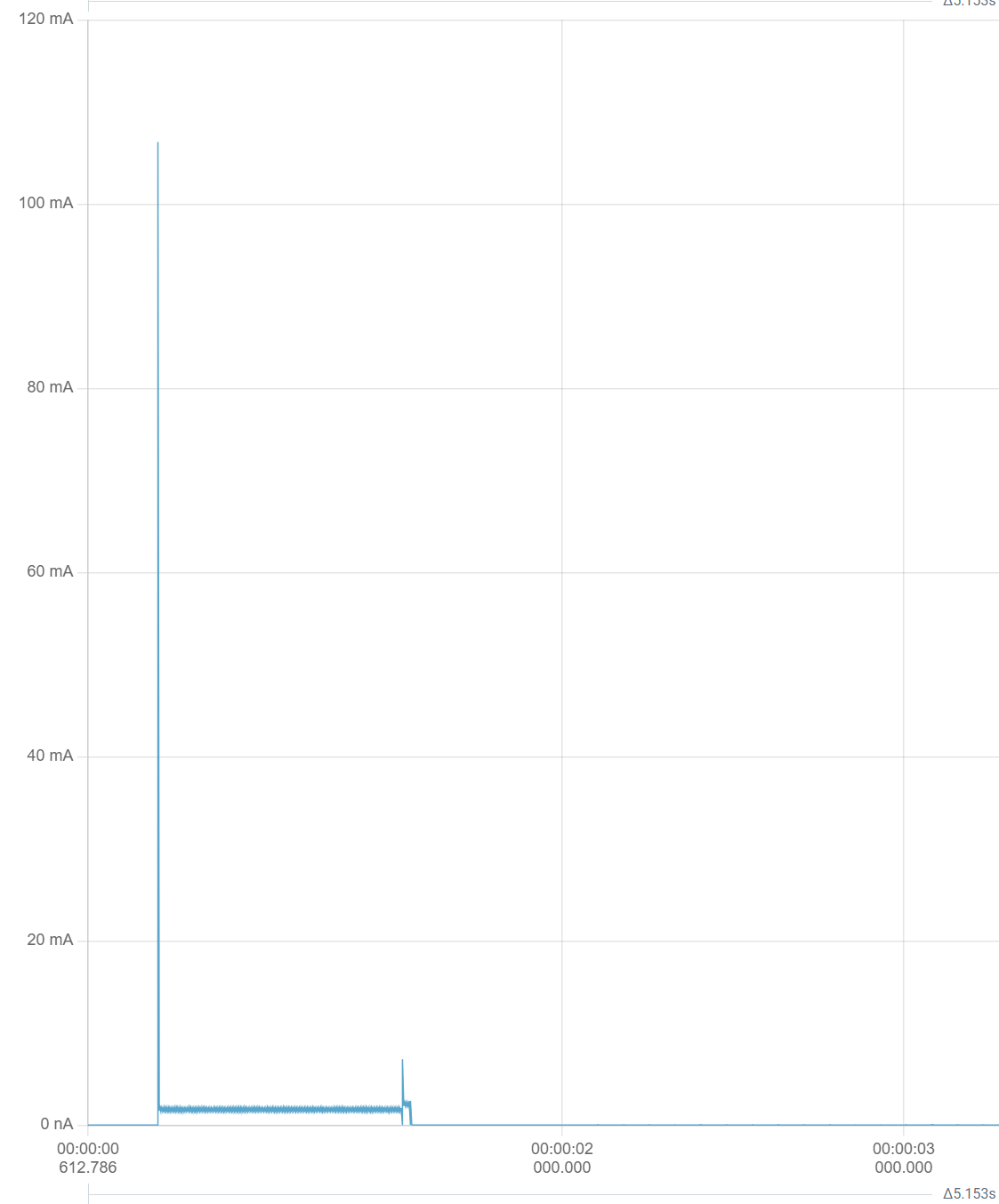
You can see, it starts off busy and before going flat.
Once the device went to sleep, the power consumption was almost non-existent!
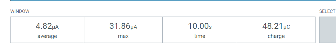
Again, this 5µ included all the electronics, including the LDO.
Now I knew what was possible when the chip was asleep.
Help from Temboo
I have been testing out this AI Coding assistant called Temboo.
The kind folks at Temboo had given me some free tokens, so I asked it to check my configuration.
It recommended a few more flags to be changed and also told me what peripherals I should disable. I followed its advice and after flashing, I saw a small reduction in the 1-minute average power.
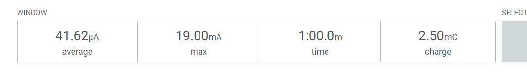
This would give 240 days from a 240mAh battery.
Whilst I reviewed the trace, I began to wonder if I was chasing the most difficult optimizations. My ADC code, after all, was using a lot of power. Here are the two reads of the ADC PINS
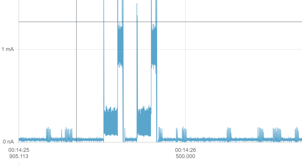
When I switch the power pin on, you can see a there is block of power consumption, which is 300µA! Nothing is actually happening here, I’m just allowing the voltage to settle. I began to wonder if 50ms was too long to wait.
That helped a little bit
At 38µA, a 240mAh battery would last for ~260 days.
That said, it still looked still far too busy when idle!
Interrupts
On a whim, I decided to post this question to Reddit’s r/embedded channel.
One user, @allo37 suggested it might be a problem with interrupts.
I was using interrupts for the reset button logic.
That led me to this post: https://devzone.nordicsemi.com/f/nordic-q-a/79239/gpio-interrupts-cause-high-current-consumption-during-sleep-on-nrf9160-and-nrf52833
Following the advice, I changed the Interrupt flag from GPIO_INT_EDGE_BOTH to GPIO_INT_LEVEL_HIGH.
The consumption dropped dramatically!
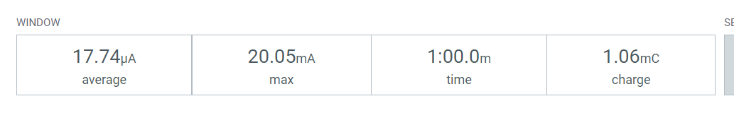
An average of 18µA was 1.5 *YEARS* on my 240mAh battery!!!
That’ll do pig, that’ll do!
I was now back in annual battery life territory, so I was very happy.
With power consumption down this low, I could now update my PCB design to incorporate a coin battery holder. This was massive.
All the code for this project is available at https://github.com/tomasmcguinness/matter-nrf-dual-temperature-sensor
Did you like reading this post?
If you found this blog post useful and want to say thanks, you’re welcome to buy me a coffee. Better yet, why not subscribe to my Patreon so I can continue making tinkering and sharing.
Be sure to check out my YouTube Channel too – https://youtube.com/tomasmcguinness
Thanks, Tom!

Leave a comment