
As I push forward on my both my Heat Pump installation and Matter Energy Manager, the next item on my list of things to Matter-ize was this: An Energy Meter
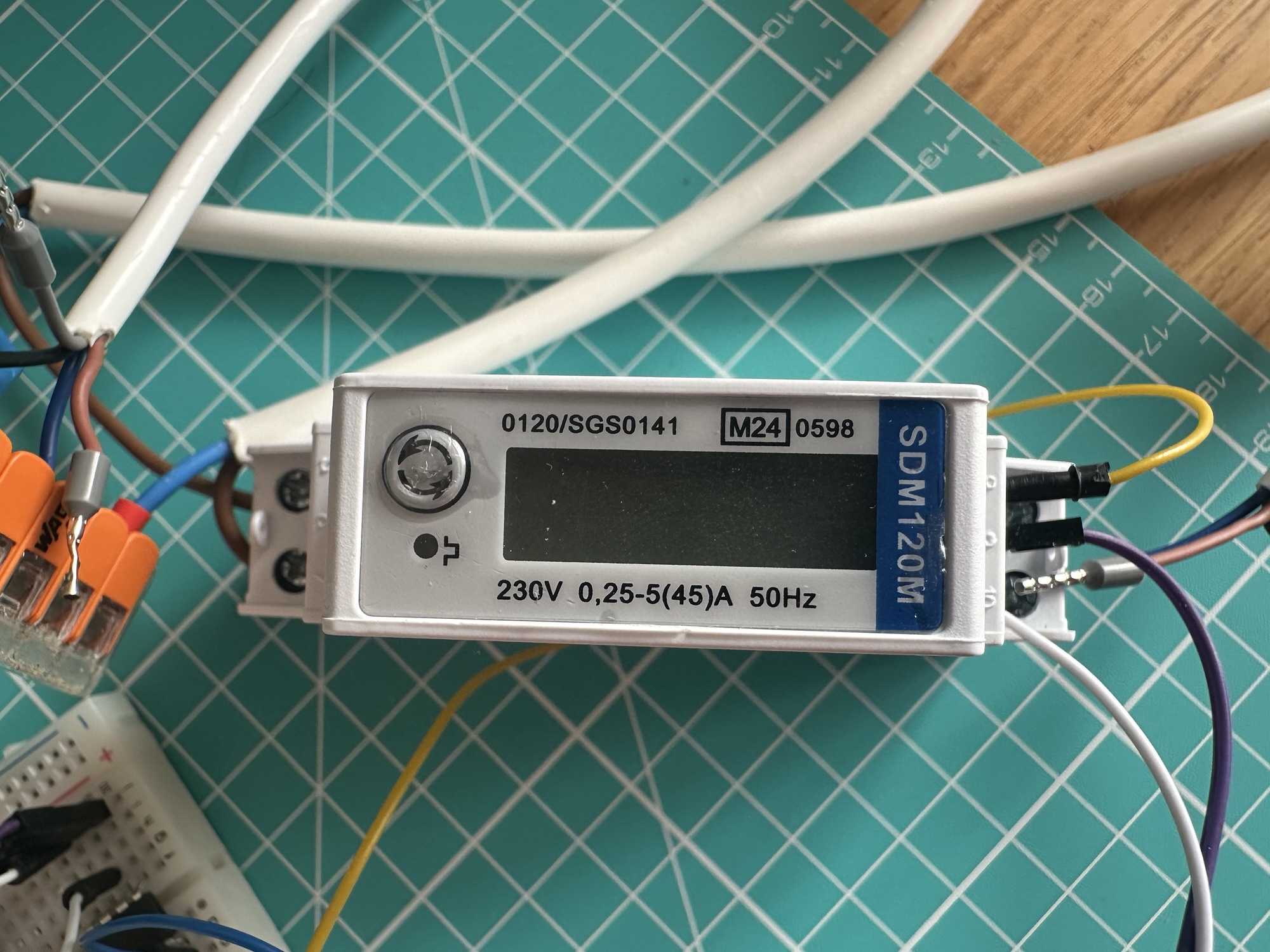
These types of meters are common in Heat Pump installations as they measure the power consumption. This then let you to compare heat out (using a heat meter) with electricity in (energy meter). This meter is MID approved, meaning it meets European standards for accuracy and reliability. The popular Open Energy Monitor platform uses these too.
The Eastron SDM120M comes in different variations, with the M meaning Modbus. There are Pulse and M-Bus models available too.
Modbus is an industrial protocol that lets one device communicate with others. It can operate over serial or network connections and involves memory registers. In the case of the 120M, it uses serial communication, specifically RS485.
Hey, didn’t I do this already?
I did! Last summer I successfully connected an ESP32-C6 to this meter by using a converter board called HW-519. This board handled the serial communication, using a MAX485 chip to speak RS485. You can read the original post here.
TL;DR; Using a TTL to RS485 board, I successfully read register values from the SDM120M
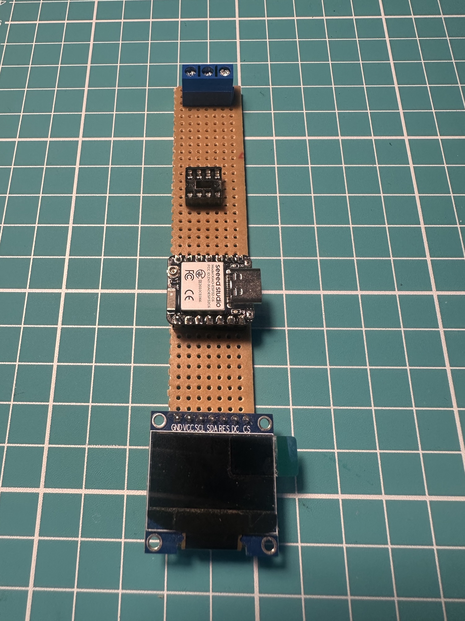
For this phase, I wanted to use the MAX485 IC directly, so I could make my own PCB.
Wiring up the MAX485
The MAX485 provides the TTL to RS485 conversion. You can find the information and data sheet over here:
https://www.analog.com/en/products/max485.html
The example diagram looked straightforward. On one side, pins 1 to 4, we had the TTL input. On the other size, we had VCC, GND and the Modbus A and B terminals.
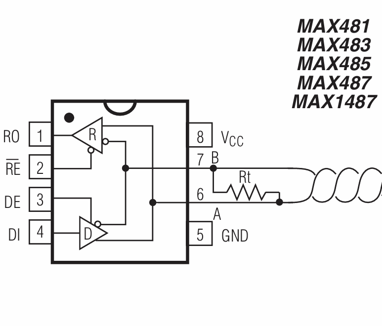
VCC and GND are easy. VCC is 5V. Most (all?) ESP32 variants will expose a 5V pin, which is powered by USB.
The resistor across A and B (Rt) is recommended to be 120kΩ. Since I don’t know if the SDM120M includes this resistor, I’ve added one.
To speak TTL, like I did with the HW-519 adapter, the ESP32 will use its TTL UART component. Setting that up is done with the UART driver.
uart_config_t uart_config = { .baud_rate = 9600, .data_bits = UART_DATA_8_BITS, .parity = UART_PARITY_DISABLE, .stop_bits = UART_STOP_BITS_1, .flow_ctrl = UART_HW_FLOWCTRL_DISABLE, };uart_param_config(MODBUS_UART, &uart_config);uart_set_pin(MODBUS_UART, TX_PIN, RX_PIN, UART_PIN_NO_CHANGE, UART_PIN_NO_CHANGE);uart_driver_install(MODBUS_UART, 256, 0, 0, NULL, 0);
We connect the TX_PIN and RX_PIN of the ESP32 to the R0 and DI pins on the IC.
The next pins we need to tackle are the RE and DE. RE is Receive Enable and DE is Driver Enable. These pins set the direction of the communication. We set RE when we want to receive and DE when we want to transmit.
We can handle this with a single GPIO. This is because receive is enabled when pulled high and DE is enabled when pulled low. This allows a single GPIO can work for transmit and receive.
// Direction control pin
gpio_config_t io_conf = {
.pin_bit_mask = (1ULL << DE_RE_PIN),
.mode = GPIO_MODE_OUTPUT,
.pull_up_en = GPIO_PULLUP_DISABLE,
.pull_down_en = GPIO_PULLDOWN_DISABLE,
.intr_type = GPIO_INTR_DISABLE,
};
gpio_config(&io_conf);
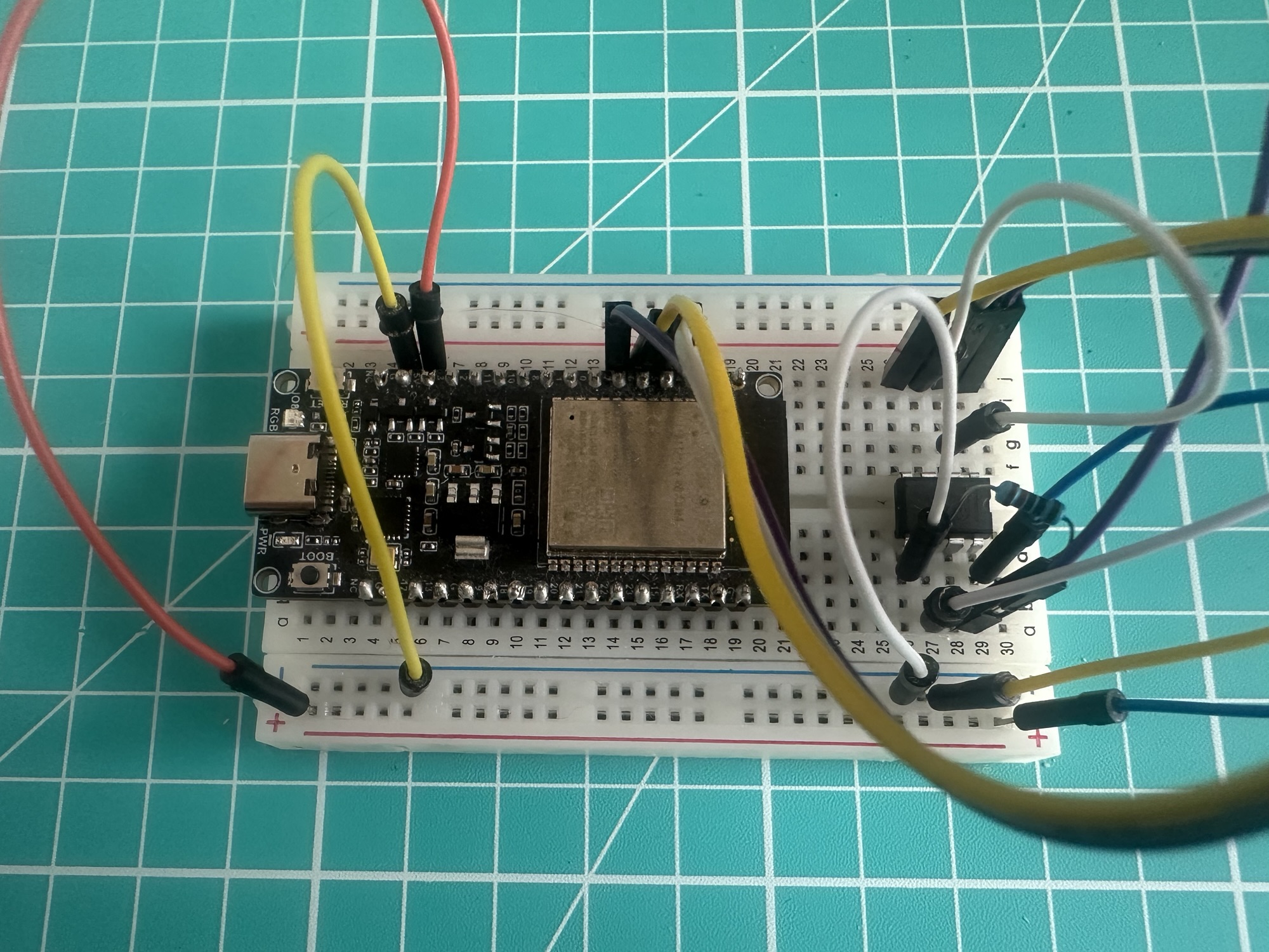
gpio_set_level(DE_RE_PIN, 0); // Start in RX modeAfter wiring it up to an ESP32 DevKit from Waveshare, it looks like this:
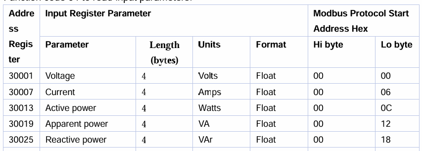
Next came reading the different Modbus registers to get valves like voltage, current etc.
Thankfully Eastron publish the register list and you can find it here:
It looks something like this
To read the value from a register, we send a read command. The core of the code looks like this
uint8_t request[8];request[0] = MODBUS_SLAVE_ADDR;request[1] = 0x04;request[2] = (reg_addr >> 8) & 0xFF;request[3] = reg_addr & 0xFF;request[4] = 0x00;request[5] = 002;uint16_t crc = crc16_modbus(request, 6);request[6] = crc & 0xFF;request[7] = (crc >> 8) & 0xFF;gpio_set_level(DE_RE_PIN, 1);vTaskDelay(pdMS_TO_TICKS(2));uart_write_bytes(MODBUS_UART, request, 8);uart_wait_tx_done(MODBUS_UART, pdMS_TO_TICKS(100));
We build up a small payload, put the DE_RE_PIN into transmit and write the values.
We then wait, and read the response
 gpio_set_level(DE_RE_PIN, 0);
 vTaskDelay(pdMS_TO_TICKS(2));

 uint8_t response[9];
 int len = uart_read_bytes(MODBUS_UART, response, 9, pdMS_TO_TICKS(1000));
So, to read voltage, we read register 0x0000
float voltage = 0;modbus_read_float_register(0, &voltage)
To read current, we read register 0x0006
modbus_read_float_register(6, ¤t)
and so on.
Displaying the values
With my code reading four values from the device, I thought it might be helpful to display them. I had used a small OLED screen in my dishwasher emulator project, so I borrowed it.
I had all the code from that project, so I adapted it for my four values. As I mentioned, I’m not pulling enough current for anything but voltage to be zero!
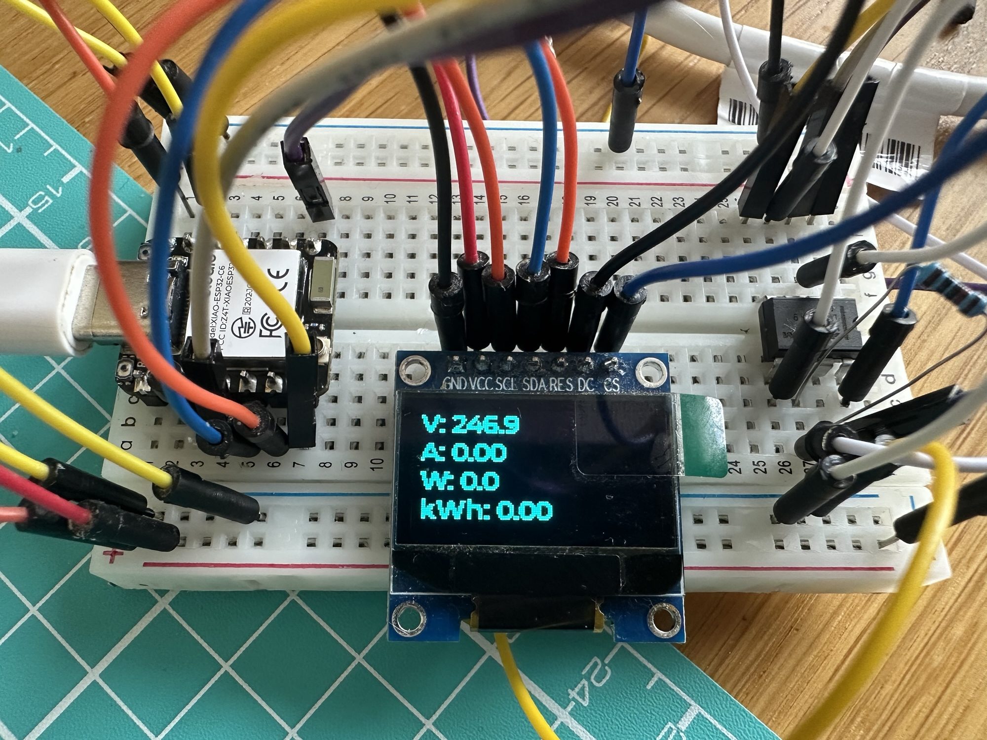
The display is implemented using LVGL library and the ESL_LVGL_PORT library. It displays four labels which get updated as the Modbus registers are read.
Exposing via Matter
The final step in this project was exposing some of these values via Matter.
This involved adding the esp-matter library via espressif’s component library.
dependencies: espressif/esp_matter: ^1.4.0
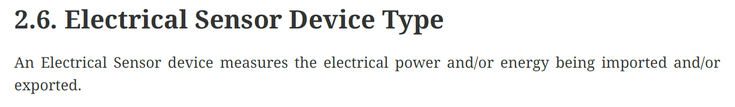
For electrical “stuff”, Matter defines an Electrical Sensor Device Type, which is perfect for this project.
Alongside the usual boiler plate code, I added the new endpoint
electrical_sensor::create(node, &electrical_sensor_config, ENDPOINT_FLAG_NONE, NULL);
I also had to create a voltage attribute, as that’s marked as optional in the specification
electrical_power_measurement::attribute::create_voltage(cluster, 0);
Finally, I had to create a new delegate for the cluster, based on ElectrialPowerMeasurementDelegate. Some Matter clusters use delegates to provide data, rather than storing them in the objects themselves. There are different reasons for this, none of which I really understand at present😋. The delegate class looked like this
namespace chip {namespace app {namespace Clusters {namespace ElectricalPowerMeasurement {class ElectricalPowerMeasurementDelegate : public Delegate}}}}
Within this delegate, I implemented a few of the methods, like GetVoltage()
 DataModel::Nullable<int64_t> GetVoltage() override {
    ESP_LOGI("EPMDelegate", "GetVoltage called");
    return mVoltage;
}
When I have a new voltage value, I store it within the delegate’s instance
mVoltage = newValue;
I tell the Matter SDK that it should report the change
MatterReportingAttributeChangeCallback(mEndpointId, ElectricalPowerMeasurement::Id, Attributes::Voltage::Id);
If the attribute is queried, the delegate’s GetVoltage will be called. We can demonstrate that using chip-tool
chip-tool electricalpowermeasurement read voltage 0x14 1
I (982473) EPMDelegate: GetVoltage called

The reading is in mV, so it appears much larger 🙂
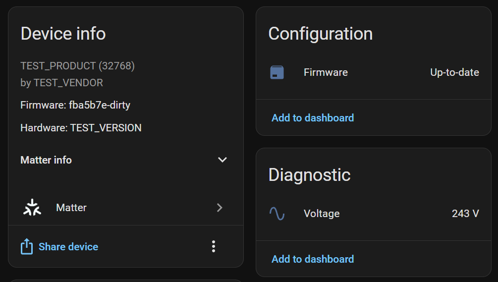
HomeAssistant also supports this Device, so I can see my voltage there too!
Code
All the code is available on Github if you want to try this yourself.
https://github.com/tomasmcguinness/matter-esp32-modbus-adapter
At present, I have to complete more of the Matter implementation and clean up the code. I need to also provide more details like a PIN out.
Next Steps
This project will hopefully grow over the coming months. Ultimately, I want to create an adapter than can interface with other Modbus devices.
Personally, I have a Solax X1 hybrid inverter, that supports Modbus. As I mentioned, I’m also getting a Kronoterm heat pump later this year, which also supports Modbus.
I need to find a good way to modularise my code, but the basics are the same. I just need to know which registers are which. This information is usually officially available, or somebody has reverse engineered it already!
Once I’ve done more testing, the next concrete step is finishing this strip-board version before I move onto PCB design.
I’m trying to think of the best way to power a device like too. I think it would need mains power (USB) to ensure the data is up-to-date.
Interested in using this?
If you’d be interested in using something like this, please do reach out. When I get to the PCB stage, I can also add a few additional boards into my order. Which makes each board cheaper too 🙂
Did you like reading this post?
If you found this blog post useful and want to say thanks, you’re welcome to buy me a coffee. Better yet, why not subscribe to my Patreon so I can continue making tinkering and sharing.
Be sure to check out my YouTube Channel too – https://youtube.com/tomasmcguinness
Thanks, Tom!

Leave a comment