
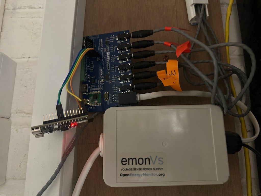
As I continue to build my Matter based Home Energy Manager, I’m always looking for ways to get more power measurements into my system. As I currently have an Open Energy Monitor system installed, I started to wonder how I might add Matter support to is.
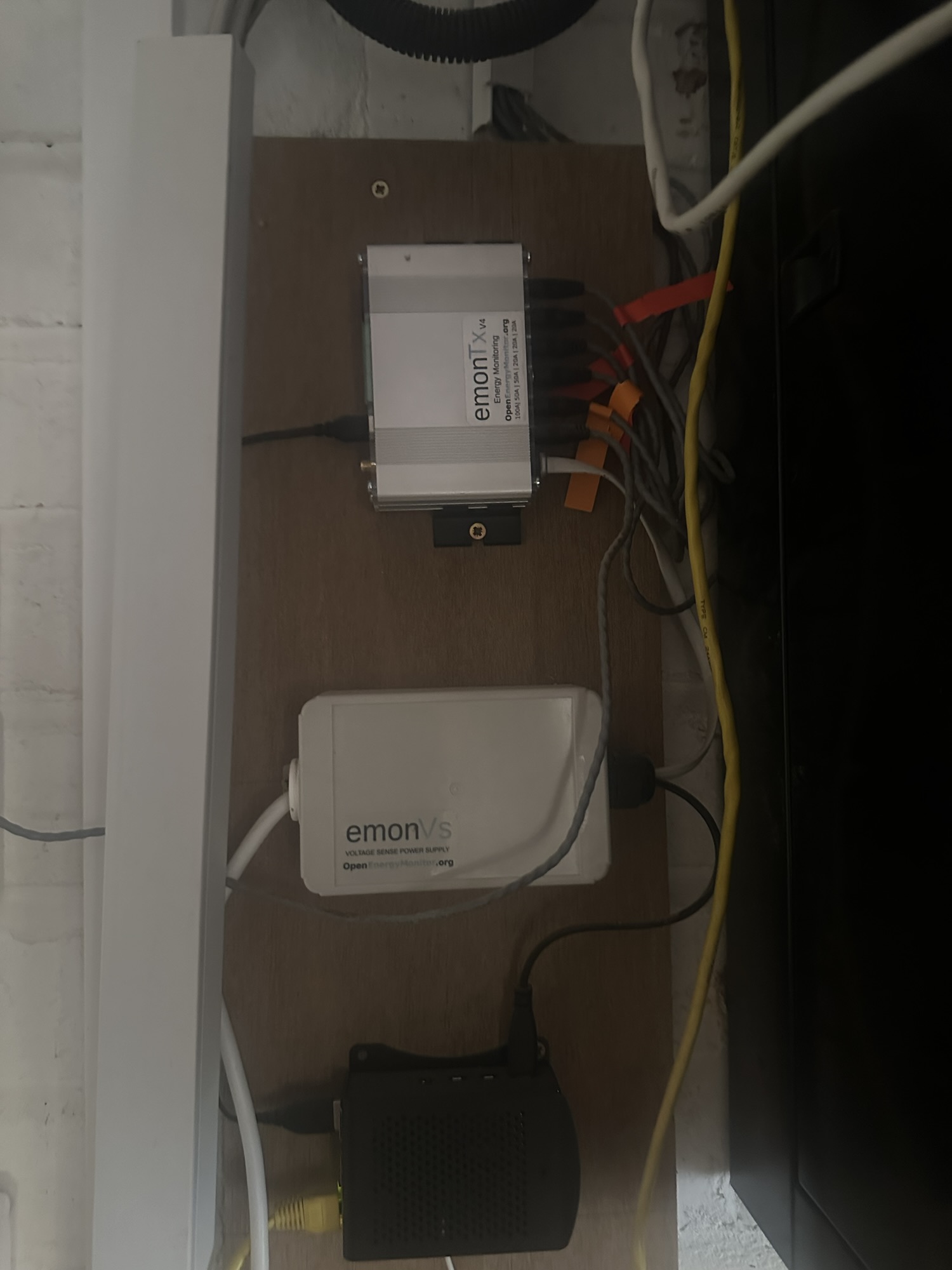
The system I have consists of three parts. The silver unit at the top is an emonTx4 and its responsible for measuring the power from six different CT clamps. Next is the emonVs, which is responsible for measuring voltage (and providing power to the emonTx). Finally, the black box at bottom is an emonPi, which hosts the Open Energy Monitor CMS itself.
The CT clamps I have installed monitor the grid, the oven, the hob and three of the ring mains circuits. I have it all connected into Home Assistant, but to be honest, I never look at the data.
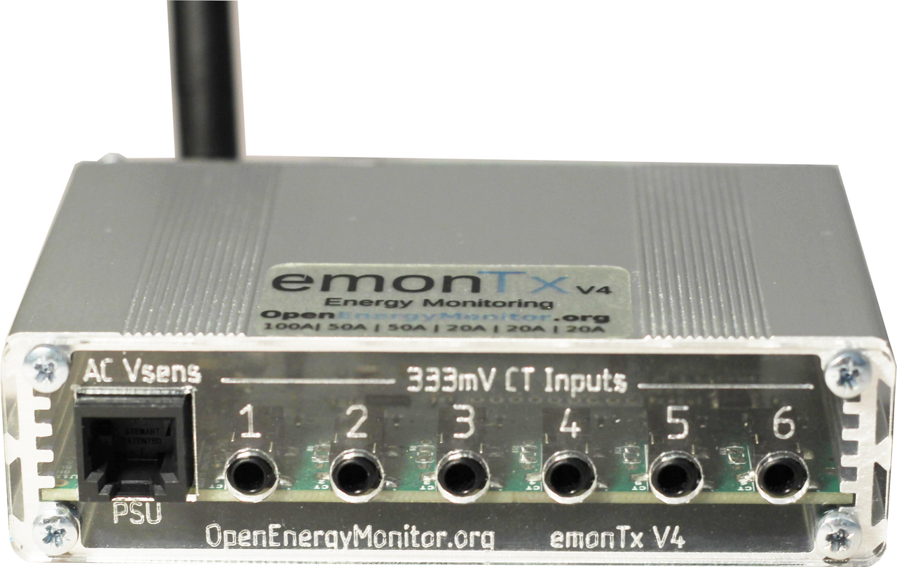
emonTx v4
This is a pretty nifty bit of hardware. It can send its measurements over USB or radio and can even be expanded with an additional six CT clamp measurements, taking the total to 12. There are certainly a few additional circuits I’d love to measurement, but I just never got around to it!
Reading the data
In my configuration, the emonTx sends data over USB directly to the emonPi. If you look at the installation image, you can see a USB cable running from the rear of the emonTx into the emonPi. From what I could find online, it just sends a string, which contains all the readings (voltage, six power measurements and six energy measurements).
This gave me a simple way to read the data. An ESP32 could be connected in the same way. It could receive the readings, parse the data and expose it via six Matter Electrical Sensors. This seemed reasonably straight forward.
However, as I was digging around the website, I came upon an interested section called Expansion Boards
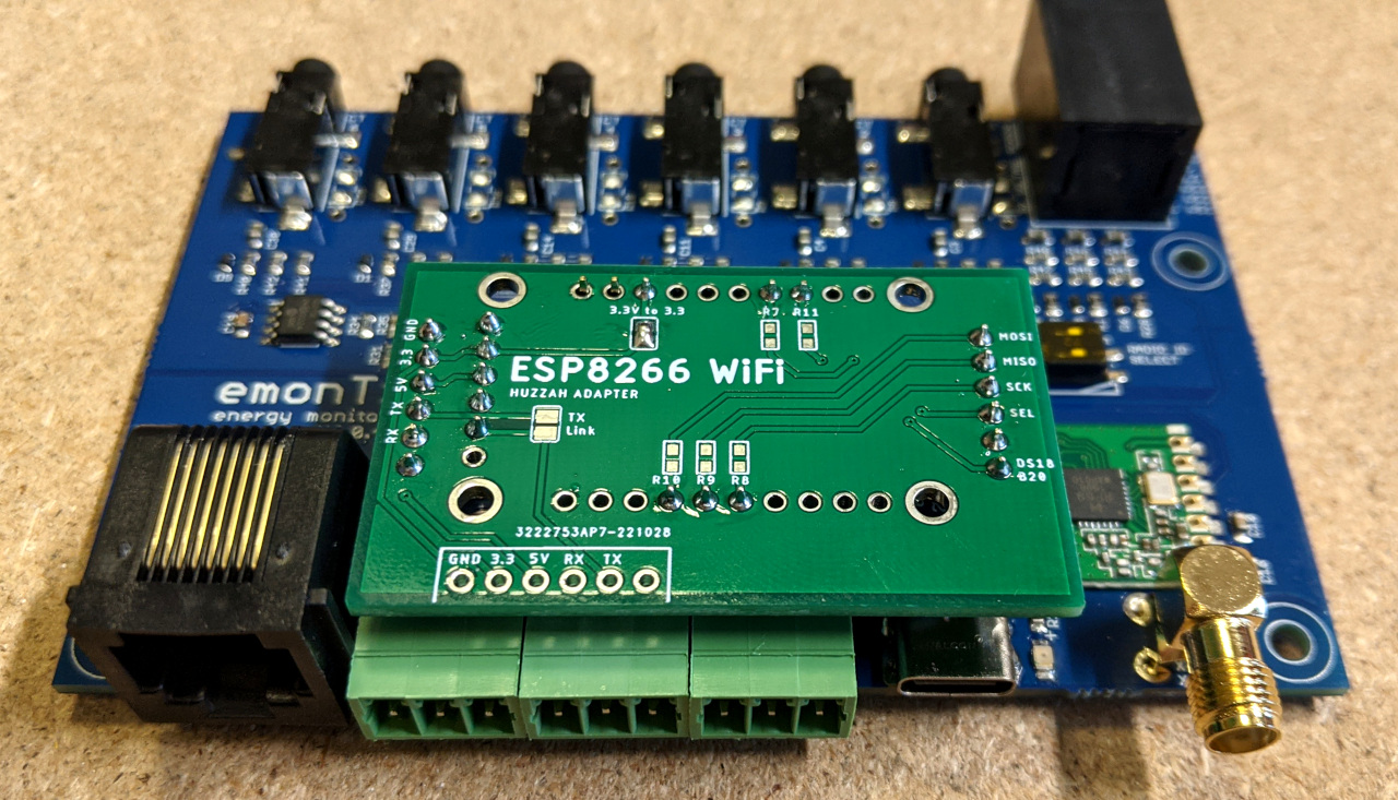
The emonTx v4 contains a set of headers, internally, which are designed for an expansion board! Here is an image from the website showing an ESP8266 expansion board installed.
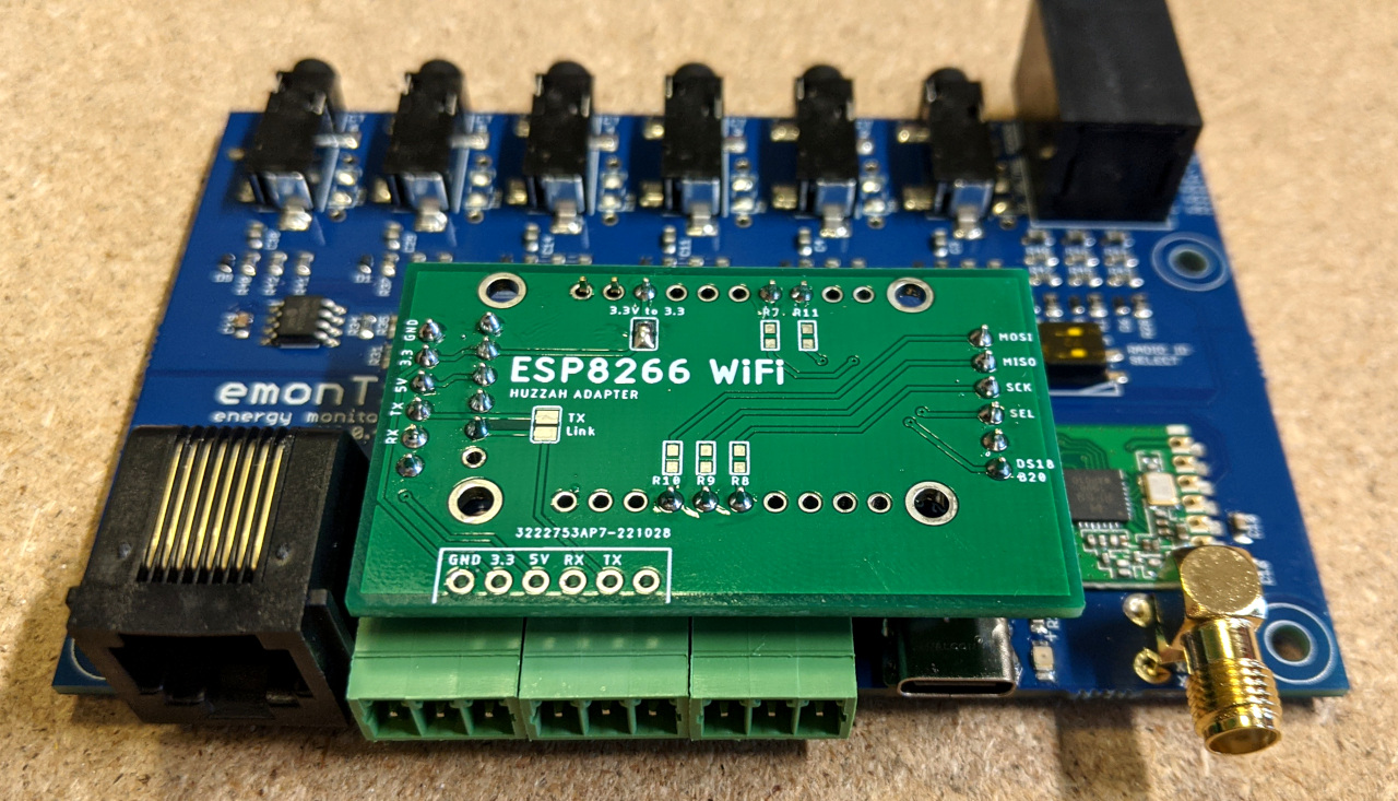
This was ever better that I had hoped! The headers supplied power and the RX & TX for UART (which is where I’d get the readings). So, all I needed to do was plug an ESP32 into these headers, parse the data stream and expose the values via Matter. Boom! Six electrical sensors available to your Matter ecosystem without any hassle!
Starting with UART
The first thing to figure out was how to read data coming over UART.
The esp-idf has an example called uart_echo, which seemed like a sensible place to start. I copied the main parts of this into my own project. It had two parts. The first was a function called echo_task, which read data from the UART buffer and played it back. The second part was app_main, which just started the task.
To run this code, I dug out my ESP32-H2-DevKitM-1. Using a DevKit to start is always the easiest option.
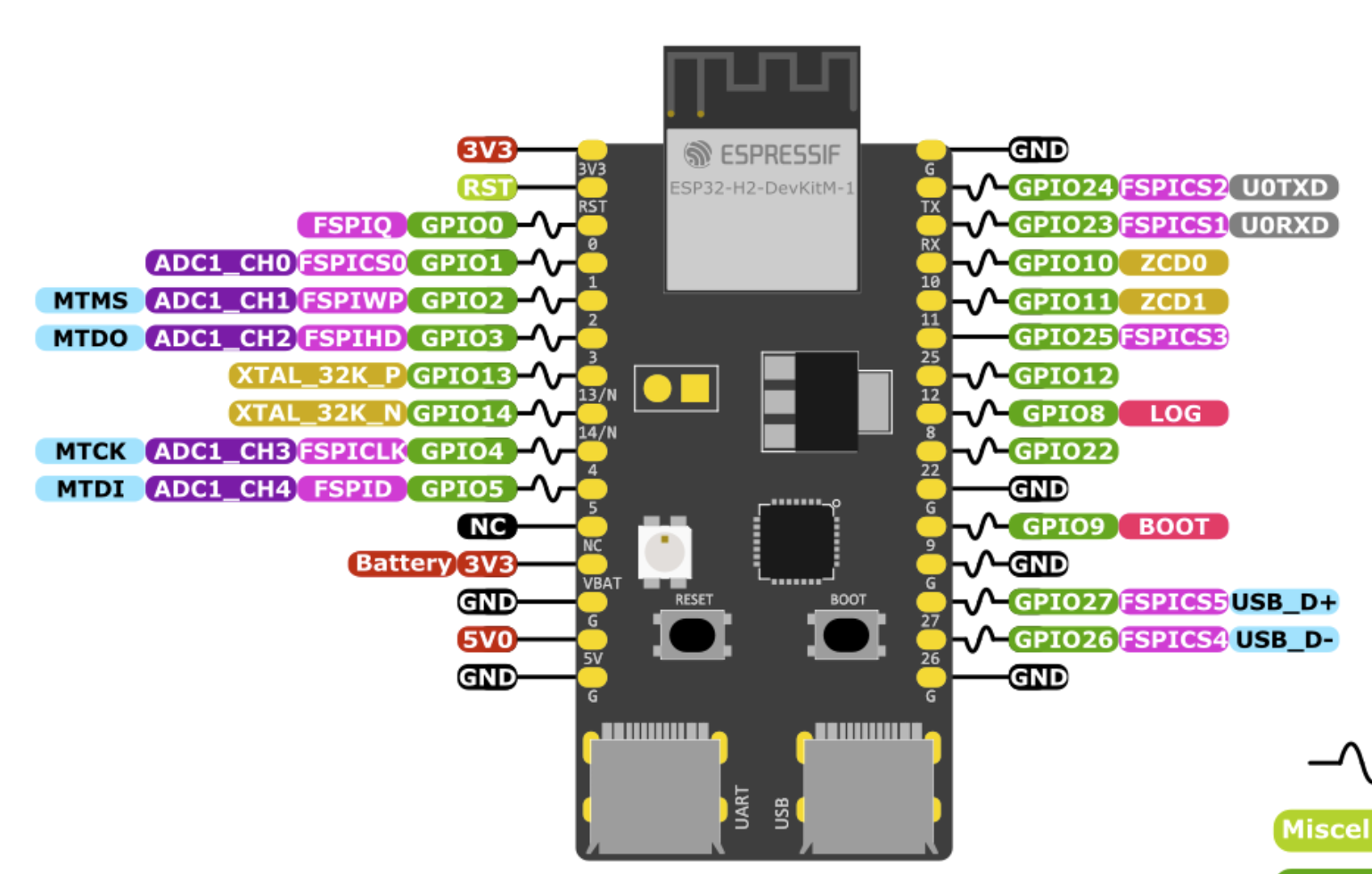
GPIO 23 & 24 on the right connect to U0TXD and U0RXD. These are connected directly to UART 0, but the ESP32 uses UART0 for logging by default, so we can’t use those. Instead, we use UART 1 with two different GPIOS. The example uses 4 & 5, so we’ll stick to those.
#define UART_PORT_NUM ((uart_port_t)1)#define UART_TXD_PIN (5)#define UART_RXD_PIN (4)#define UART_TASK_STACK_SIZE (4096)#define UART_BAUD_RATE (115200)
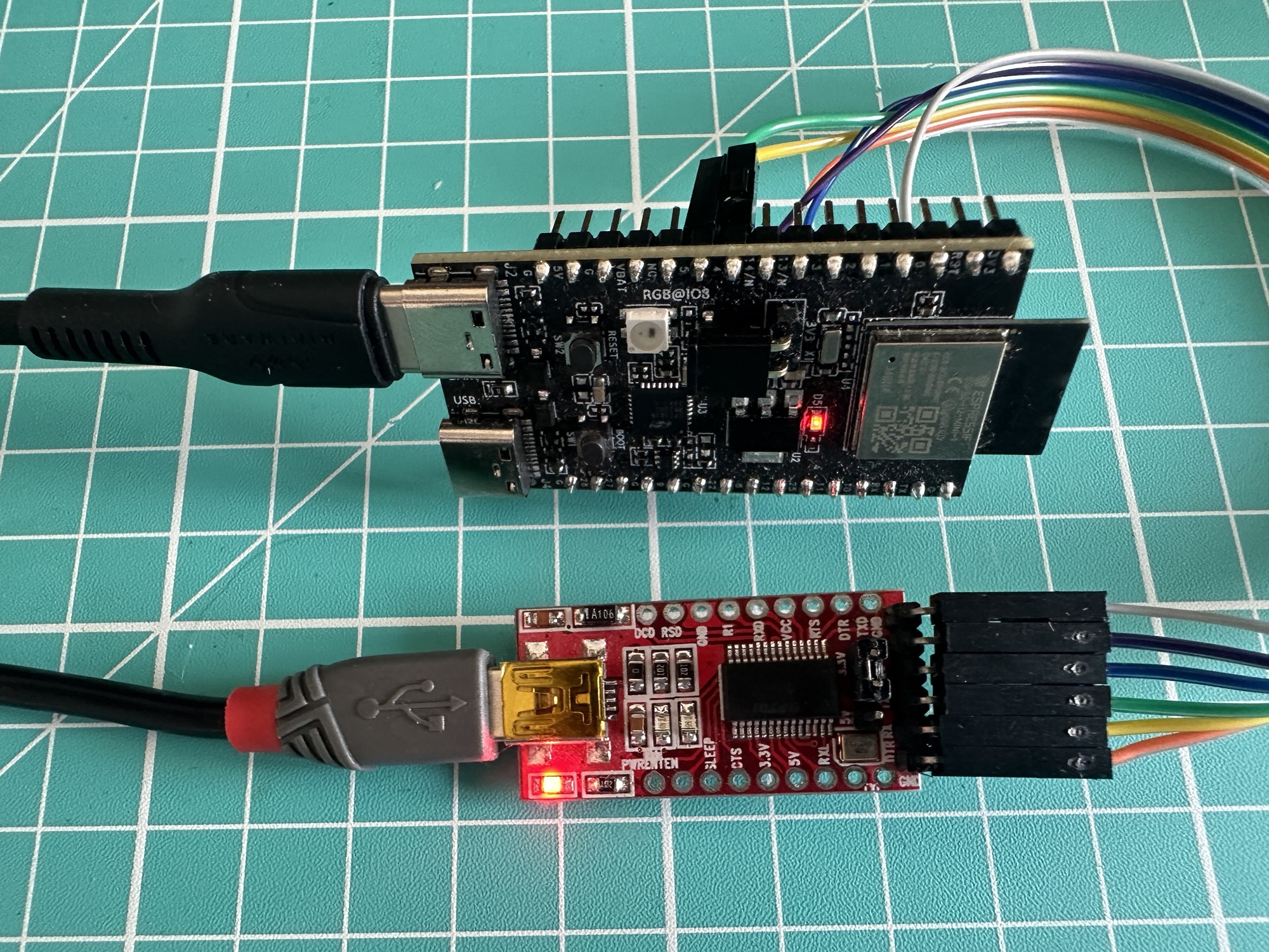
To test the code, I connected a USB->UART converter board (a YP-05), which I had from years back when I flashed Shelly 1 devices with Tasmota :).
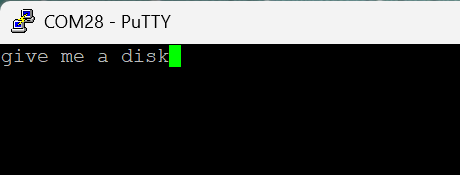
I used the Putty application to send some text (bonus points if you name the movie this is from)
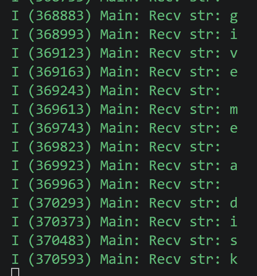
Character by character, on the ESP32-H2 side, the text is logged!
Off to a good start!
Data from the emonTx
With my UART connection working, I now needed to expand my code to read and understand an actual emonTx payload. This took a big of digging, but eventually I found what I could expect.
MSG:1,Vrms:240.00,P1:432,P2:216,P3:217,P4:86,P5:87,P6:87,E1:0,E2:0,E3:0,E4:0,E5:0,E6:0,T1:14.75,T2:14.50,T3:14.50,pulse:0MSG:2,Vrms:240.00,P1:12,P2:5,P3:5,P4:2,P5:3,P6:2,E1:0,E2:0,E3:0,E4:0,E5:0,E6:0,T1:14.62,T2:14.50,T3:14.50,pulse:0MSG:3,Vrms:240.00,P1:11,P2:5,P3:5,P4:2,P5:3,P6:2,E1:0,E2:0,E3:0,E4:0,E5:0,E6:0,T1:14.75,T2:14.50,T3:14.50,pulse:0MSG:4,Vrms:240.00,P1:11,P2:5,P3:5,P4:2,P5:3,P6:2,E1:0,E2:0,E3:0,E4:0,E5:0,E6:0,T1:14.75,T2:14.50,T3:14.50,pulse:0
Each line represents some data. Vrms is the voltage, P1 to P6 represents the power of each CT clamp, E1 to E6 represents the energy in Wh. T1 to T3 represents the three temperature sensor values and pulse is the pulse counter.
To start, I focused on Vrms and P1 to P6.
I added a new function called emontx4_task, which buffers up the incoming data until a newline character is received. It then passes the buffer to be parsed.
while (1) { if (uart_read_bytes(UART_PORT_NUM, &ch, 1, portMAX_DELAY) != 1) continue; if (ch == '\n') { line[pos] = '\0'; emontx4_reading_t r; if (parse_emontx4(line, &r)) { // strtok modifies line; pos reset below ESP_LOGI(TAG, "MSG:%d Vrms:%.2f P:%d,%d,%d,%d,%d,%d E:%d,%d,%d,%d,%d,%d", r.msg, r.vrms, r.p[0], r.p[1], r.p[2], r.p[3], r.p[4], r.p[5], r.e[0], r.e[1], r.e[2], r.e[3], r.e[4], r.e[5]); } pos = 0; } else if (ch != '\r' && pos < BUF_SIZE - 1) { line[pos++] = (char)ch; }}
The parse_emontx4 function checks that the buffer starts with MSG: and the splits the line by comma and then colon, breaking it up into the key/value pairs and populating a type called emontx4_reading_t
typedef struct { int msg; float vrms; int p[6]; int e[6];} emontx4_reading_t;
if (strcmp(key, "MSG") == 0) out->>msg = atoi(val);else if (strcmp(key, "Vrms") == 0) out->>vrms = strtof(val, NULL);else if (strcmp(key, "P1") == 0) out->>p[0] = atoi(val);else if (strcmp(key, "P2") == 0) out->>p[1] = atoi(val);else if (strcmp(key, "P3") == 0) out->>p[2] = atoi(val);else if (strcmp(key, "P4") == 0) out->>p[3] = atoi(val);else if (strcmp(key, "P5") == 0) out->>p[4] = atoi(val);else if (strcmp(key, "P6") == 0) out->>p[5] = atoi(val);else if (strcmp(key, "E1") == 0) out->>e[0] = atoi(val);else if (strcmp(key, "E2") == 0) out->>e[1] = atoi(val);else if (strcmp(key, "E3") == 0) out->>e[2] = atoi(val);else if (strcmp(key, "E4") == 0) out->>e[3] = atoi(val);else if (strcmp(key, "E5") == 0) out->>e[4] = atoi(val);else if (strcmp(key, "E6") == 0) out->>e[5] = atoi(val);
It finally lots the values in a string. So, for example, sending the first example in the list via PUTTY yields

The Matter side of things
With six power readings now available, I turned my attention the Matter side of things. The setup here is pretty boiler plate, with the exception of the delegate needed for electrical power measurements. The structure of the Matter endpoints will be simple; one Electrical Sensor device type per CT clamp. I added code to create *one* electrical sensor to get me started.
node::config_t node_config;node_t *node = node::create(&node_config, app_attribute_update_cb, app_identification_cb);ABORT_APP_ON_FAILURE(node != nullptr, ESP_LOGE(TAG, "Failed to create Matter node"));static ElectricalSensorDelegate electrical_sensor_delegate;electrical_sensor_delegate.set_active_power(999);// Create and attach six electrical sensor devices//electrical_sensor::config_t electrical_sensor_config;electrical_sensor_config.electrical_power_measurement.feature_flags = electrical_power_measurement::feature::alternating_current::get_id();electrical_sensor_config.electrical_power_measurement.delegate = &electrical_sensor_delegate; endpoint_t *electrical_sensor_1_ep = electrical_sensor::create(node, &electrical_sensor_config, ENDPOINT_FLAG_NONE, NULL);ABORT_APP_ON_FAILURE(electrical_sensor_1_ep != nullptr, ESP_LOGE(TAG, "Failed to create electrical_sensor endpoint"));esp_err_t err = esp_matter::start(app_event_cb);ABORT_APP_ON_FAILURE(err == ESP_OK, ESP_LOGE(TAG, "Failed to start Matter, err:%d", err));
The ElectricalSensorDelegate is what serves the values to the Electrical Sensor’s Power Measurement cluster. I set an initial active power value of 999W to start me off.
I then tested it by commissioning the H2 using the chip-tool and querying the active power:
chip-tool electricalpowermeasurement read active-power 0x31 0x01
and it yielded the expected result, converted from W to mW!

I then expanded the setup to include five other electrical sensors by creating a loop and an array of delegates
for (int i = 0; i < 6; i++){ electrical_sensor::config_t sensor_config; sensor_config.electrical_power_measurement.feature_flags = electrical_power_measurement::feature::alternating_current::get_id(); sensor_config.electrical_power_measurement.delegate = &g_delegates[i]; endpoint_t *ep = electrical_sensor::create(node, &sensor_config, ENDPOINT_FLAG_NONE, NULL); ABORT_APP_ON_FAILURE(ep != nullptr, ESP_LOGE(TAG, "Failed to create electrical_sensor endpoint %d", i + 1));}
The last piece of the flow was to then push the values read from the emonTx into the delegates
uint16_t vrms_tenths = (uint16_t)(r.vrms * 10.0f);for (int i = 0; i < 6; i++){ g_delegates[i].set_voltage(vrms_tenths); g_delegates[i].set_active_power((int16_t)r.p[i]);}
To test this, I sent through the sample MSG and queries some of the active-power readings on the different endpoints. Endpoint 0x02 yielded the 216W figure, which was brilliant!

Connecting to the real thing
Whilst same data is great, real data is better! The next step was to start reading from my actual emonTx. This would involve taking off the cover and wiring up my ESP32 to the actual outputs. I started by taking the emonTx out of its shell.
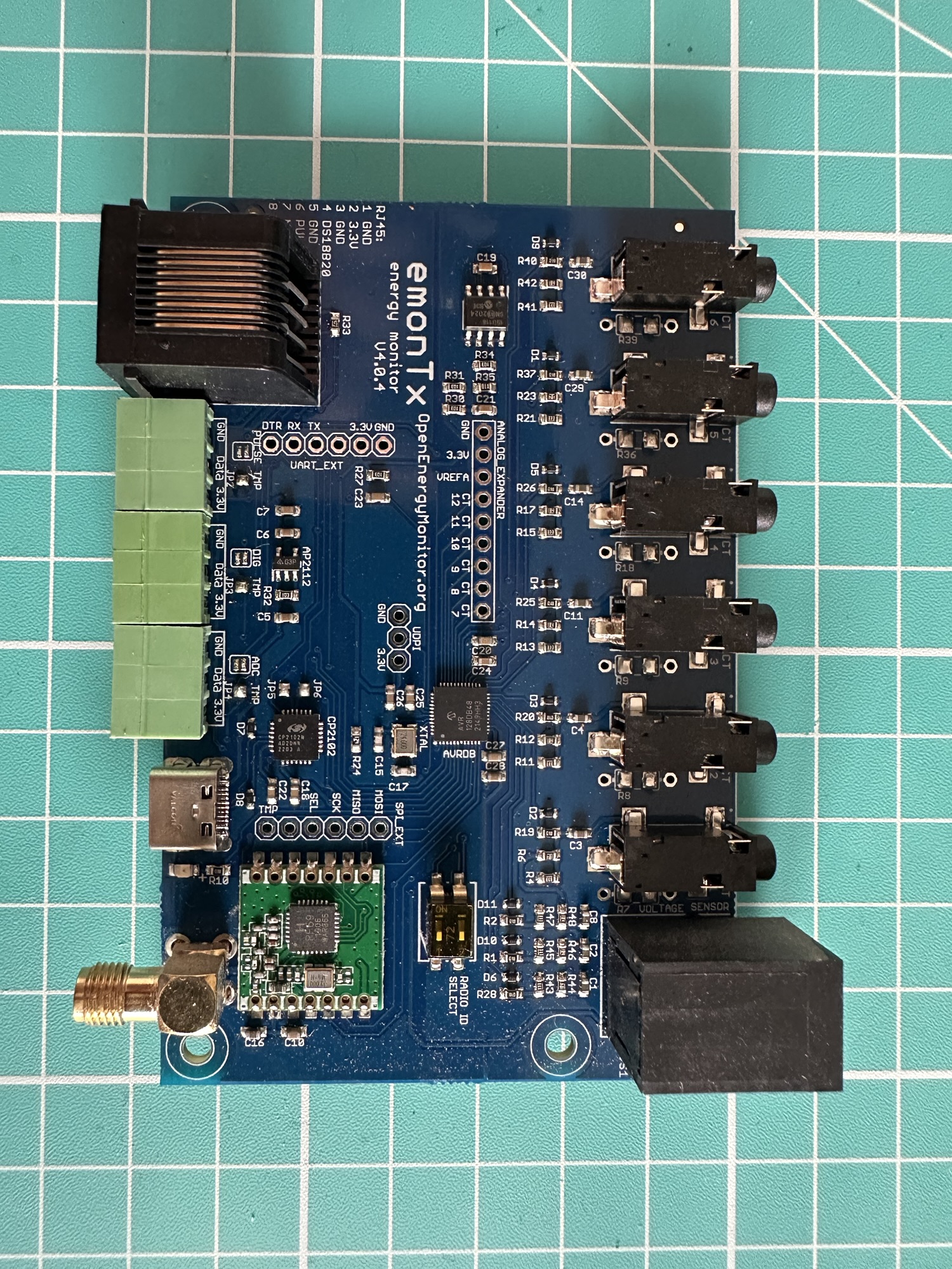
You can see the 6 UART_EXT holes beside the large black connector block in the bottom left. This meant I needed to solder in a header first, which wasn’t what I was expecting. Thankfully it was easy to remedy!
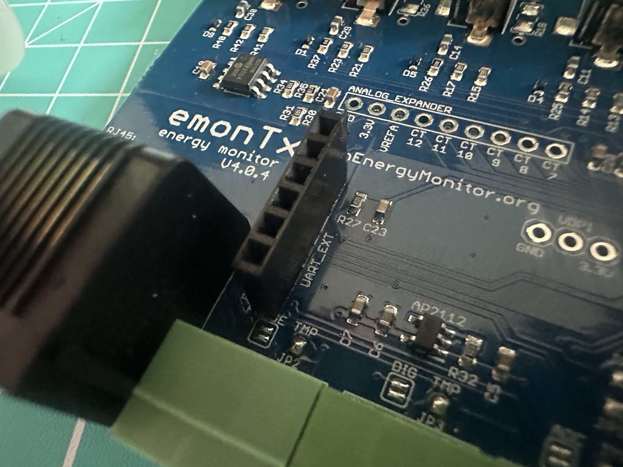
After that, I connected the DevKit to the new socket, mimicking the connection to the UART adapter.
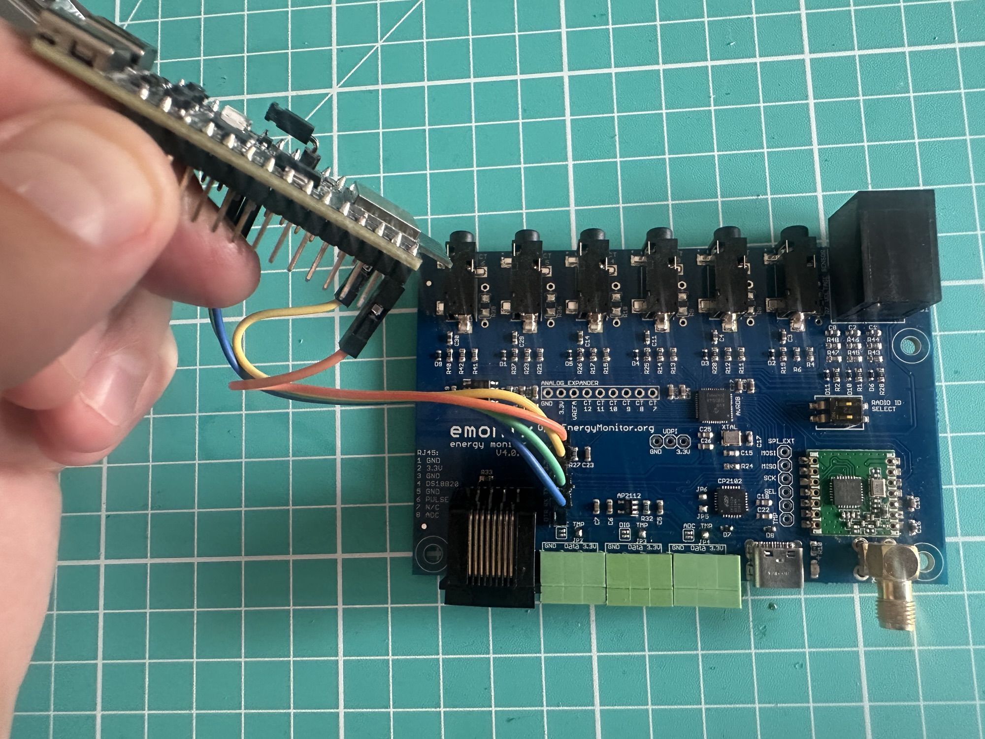
Whilst I couldn’t return the board to its housing (the jumpers protruded too much), I knew I could I just reconnect everything and power it up, which I did!
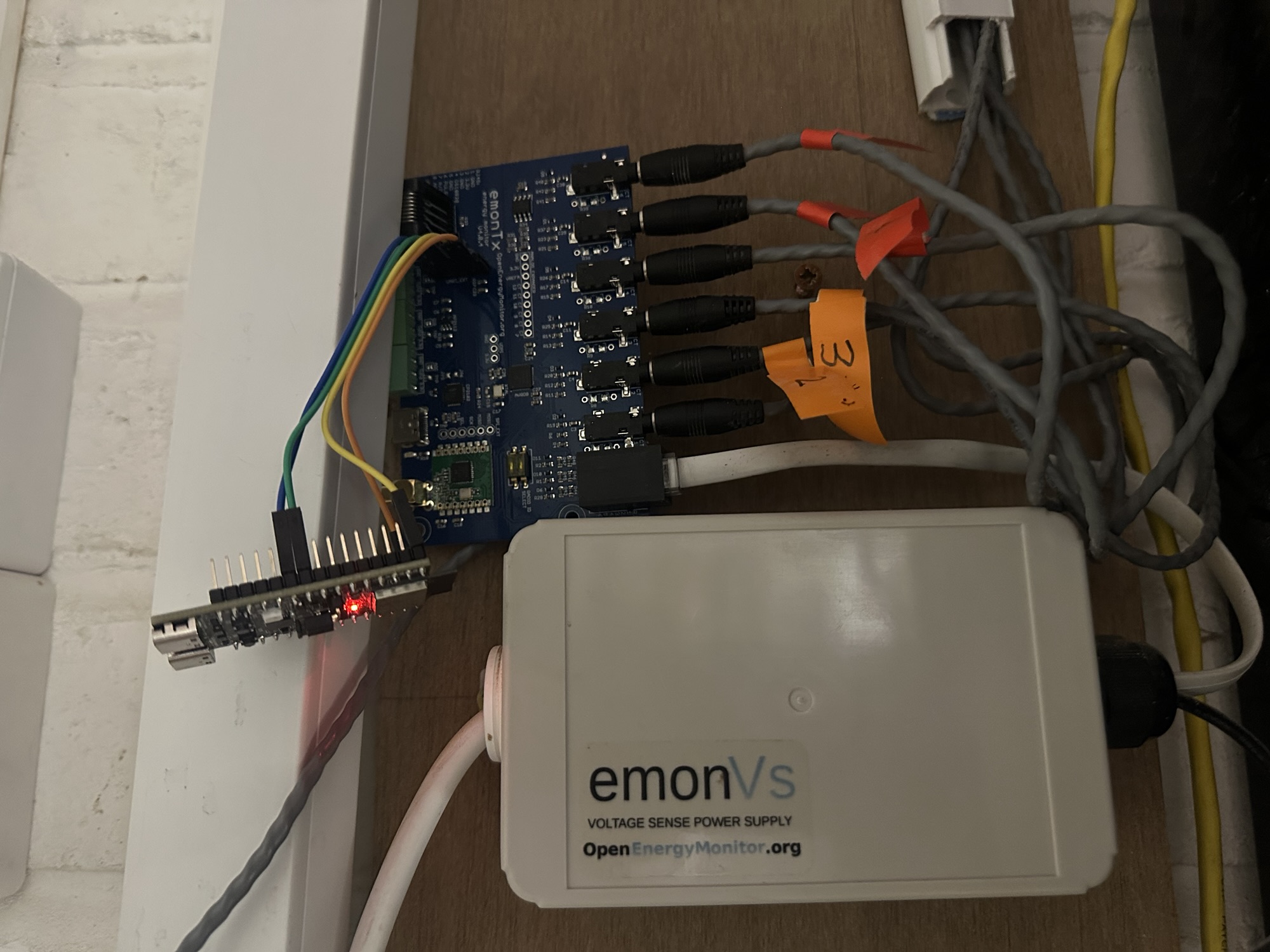
Eureka!
Whilst my devkit had power and it was responding to chip-tool commands, none of clusters had values. For example, the active power on endpoint 0x01 read as null, meaning it had been populated.

I had no way to remotely debug this, so I took out my laptop and got ready to head down to the garage to try and debug my ESP32’s code.
Then I had little idea. I quickly ran down to the garage and swapped the TX and RX pins. Lo and behold…

It worked! The Electrical Power Measurement cluster on Endpoint 0x1 had a value!
I then compare the readings to what my emonPi was recording. 34W for the grid vs the 31W endpoint 0x1 reported.
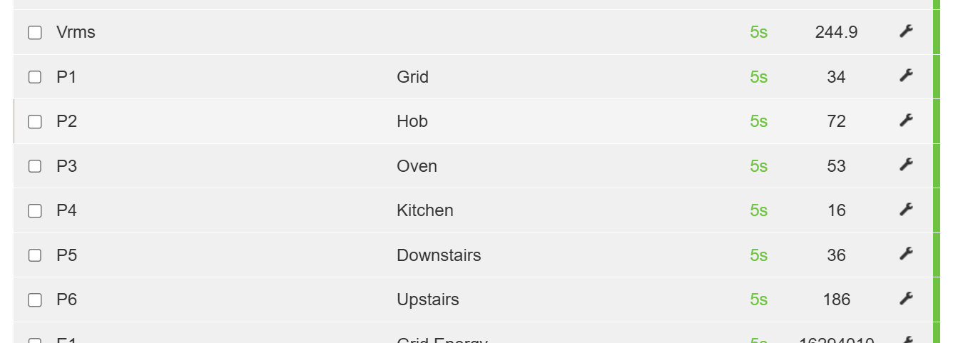
This was close enough!
Now that I’m looking at the loop figures, I’m not sure they are right. 36W for the downstairs seems low, especially as the kids are watching TV right now. I need to check the clamps are on the wires, but that is a job for another day!
Adding to my Home Energy Manager
The last thing for me to do was add the device to my Matter based Home Energy Manager (meaning I didn’t need the Shelly EM after all!).
Unfortunately, I couldn’t make this happen due to some IPv6 issues in my network. Whilst my Energy Manager has no issue commissioning WiFi or Ethernet connected devices, it can’t seem to handle a Thread device. I might just switch over to an S3 or C6 and use WiFi if this problem persists.
Like my wattage measurements, a problem for another day!
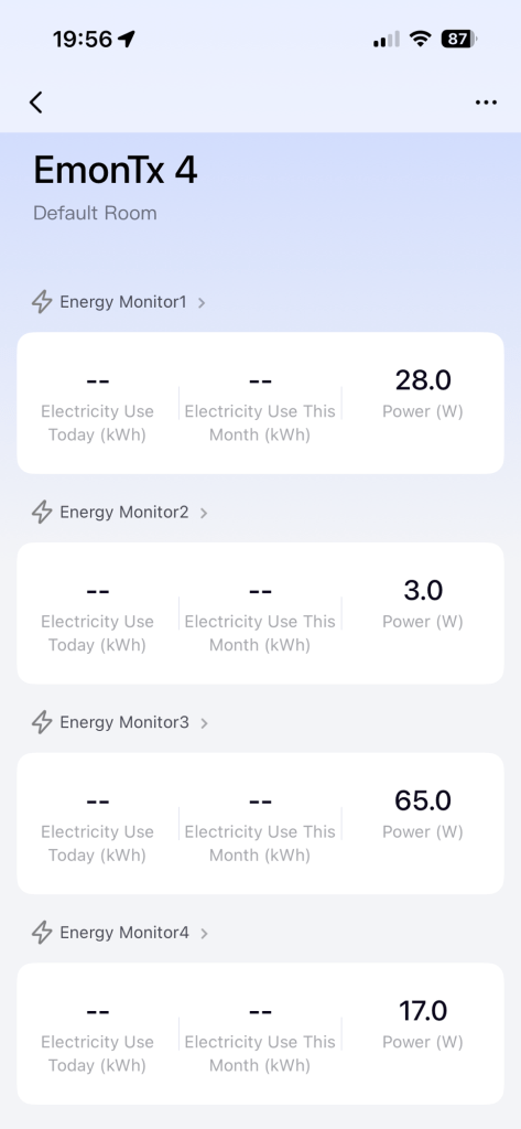
However, this is how it looks when paired with the Aqara Hub – only power is configured and it looks great!
Update (31st May 2026)
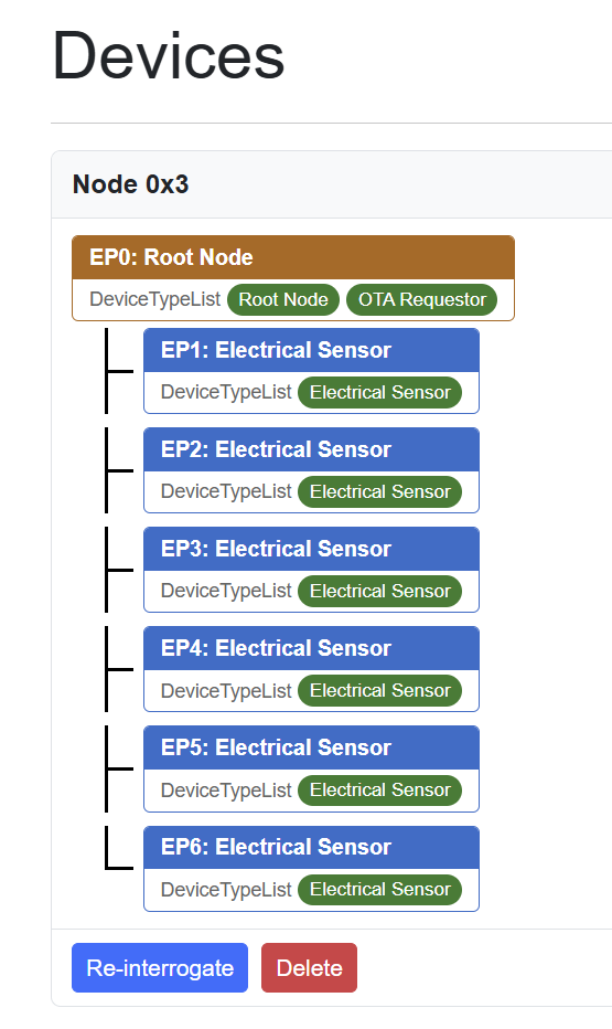
After a lot of debugging of IPv6, I figured out what was preventing my Home Energy Manager from commissioning a thread device: Multicast packets. Anyway. This is how it looks now!
Summary
In this post, I show how I used the Expansion header on my OpenEnergyMonitor emonTx v4 to add support for the Matter smart protocol.
I would like to get the board back into its enclosure, so I will probably try an ESP32-H2 supermini board (very small) instead of the DevKit. I may also get a PCB made up.
All the code is available on Github – https://github.com/tomasmcguinness/matter-esp32-emontx4-expansion/
If you want to follow my adventures in Matter & Home Energy Management, be sure to subscribe
Did you enjoy this post?
If you found this blog post useful and want to say thanks, you’re welcome to buy me a coffee.
Be sure to check out my YouTube Channel too – https://youtube.com/tomasmcguinness
Thanks,
Tom!

Leave a Reply