A few weeks ago, I designed a simple breakout board for the MinewSemi ME54B01 module.
Whilst I had one of the DevKits, I wanted to go through the exercise of designing my own PCB, with a battery compartment.
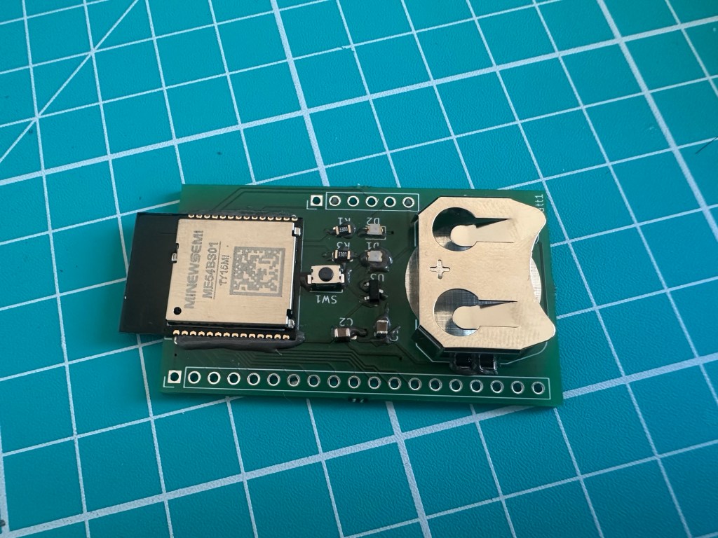
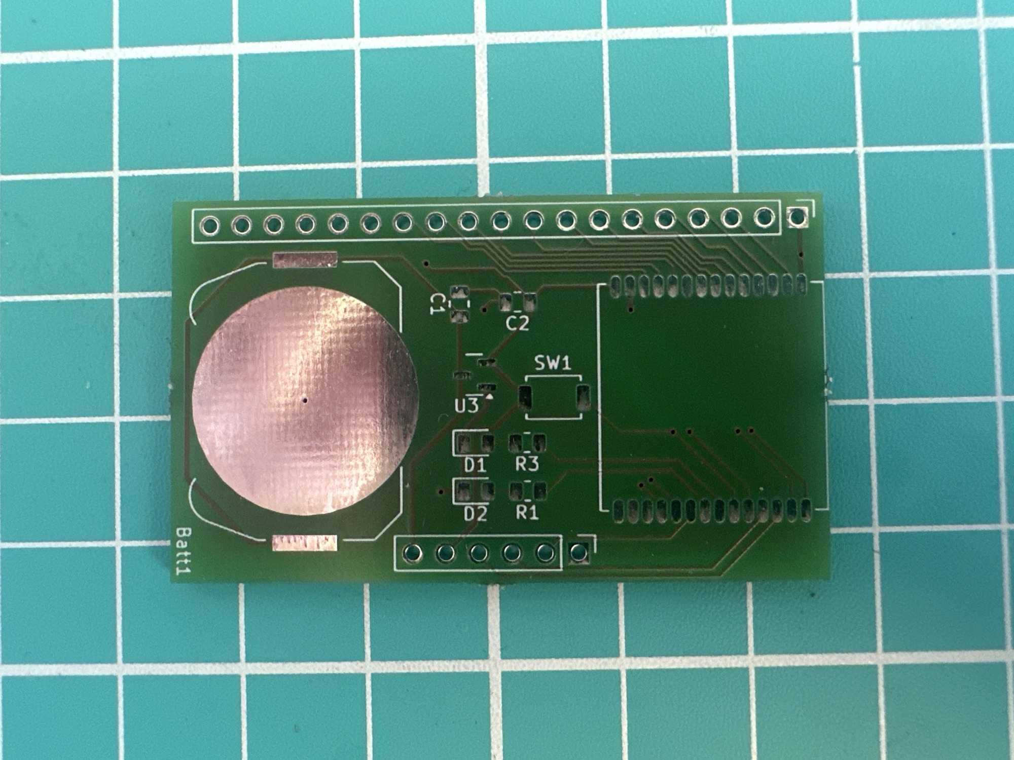
I used KiCad to do the schematic and PCB layout and after waiting a few weeks, Aisler.net delivered my boards! Not much going on, just a coin battery holder, two LEDs, a button and the module. Far from complex, but it tested my skills!
Assembly
As I was self-assembling, I started with some solder paste on the board, before positioning the ten components.
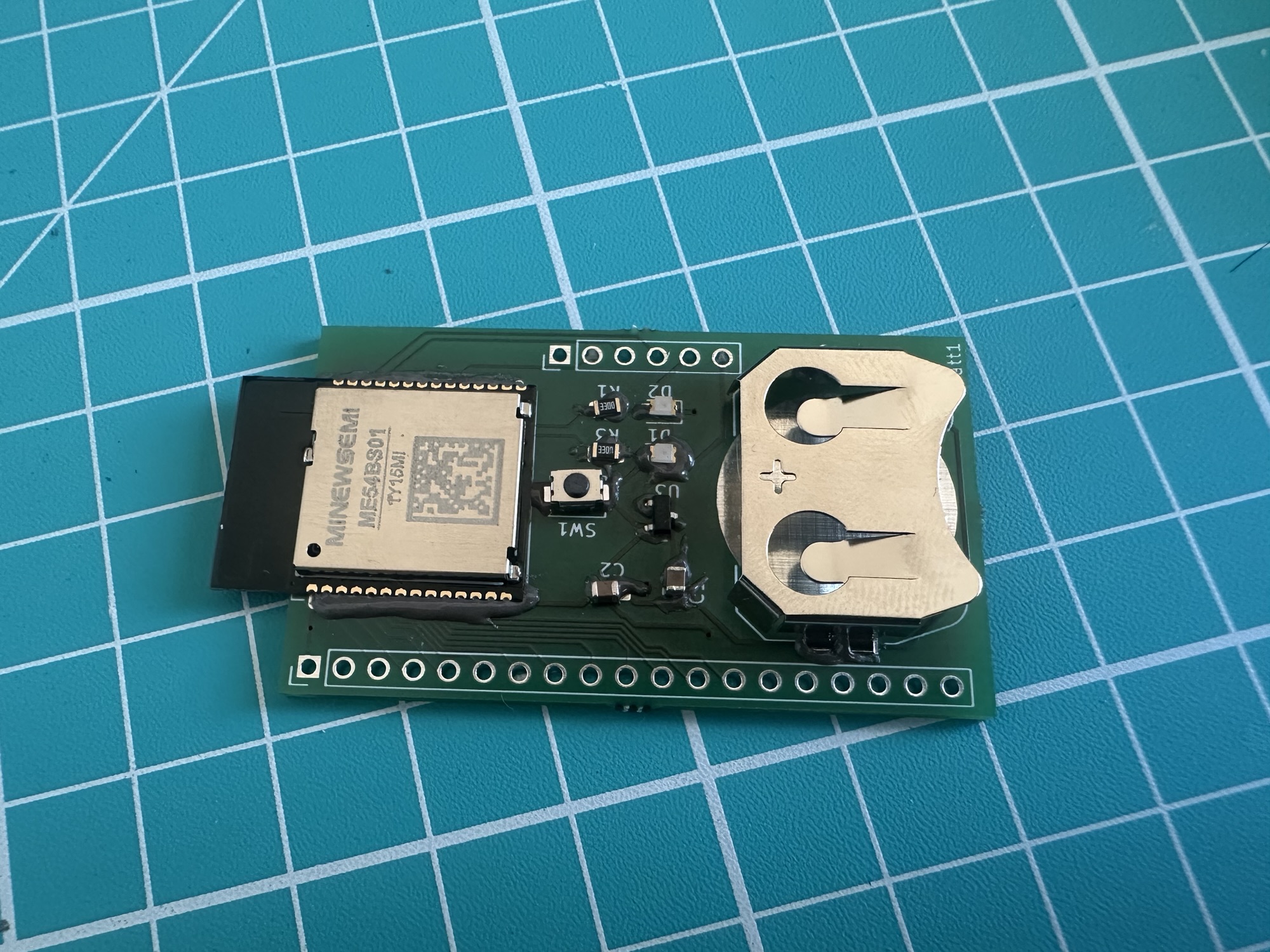
I then popped it on my little MHP50 hot plate for about 30 seconds.
Once the solder paste had all melted, I used my Pinecil soldering iron to clean up the module’s connections. There were a few solder bridges I needed to remove. This involved plenty of flux and running the tip up and down a few times until each pad had nice coverage.
Flashing
For my board, I created a simple application that blinked the two on-board LEDs in an alternating pattern. If this worked, I was confident my board was in good shape.
I started by hooking up the board to my JLink programmer. For this, I used my trusty pogo clip.
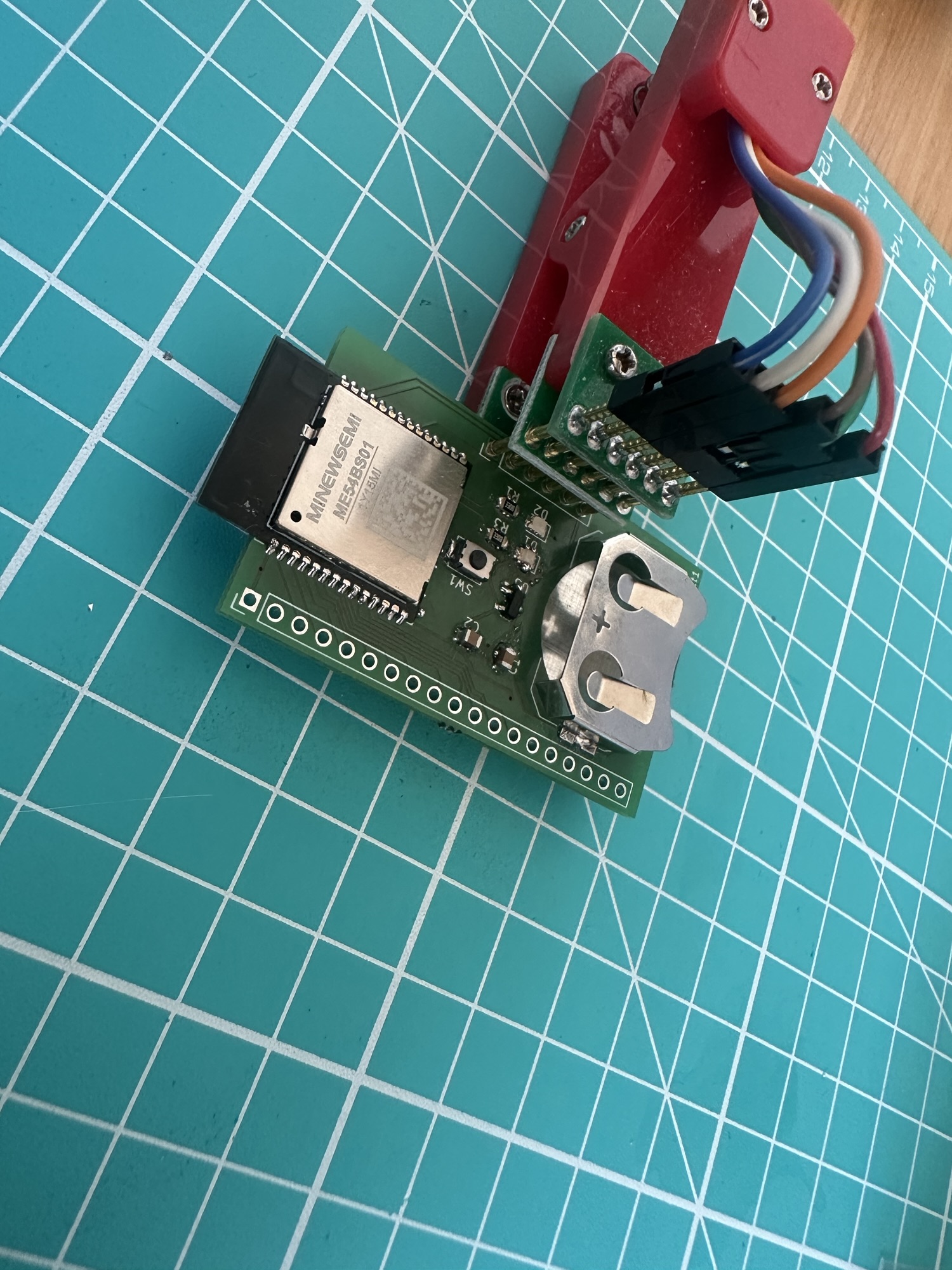
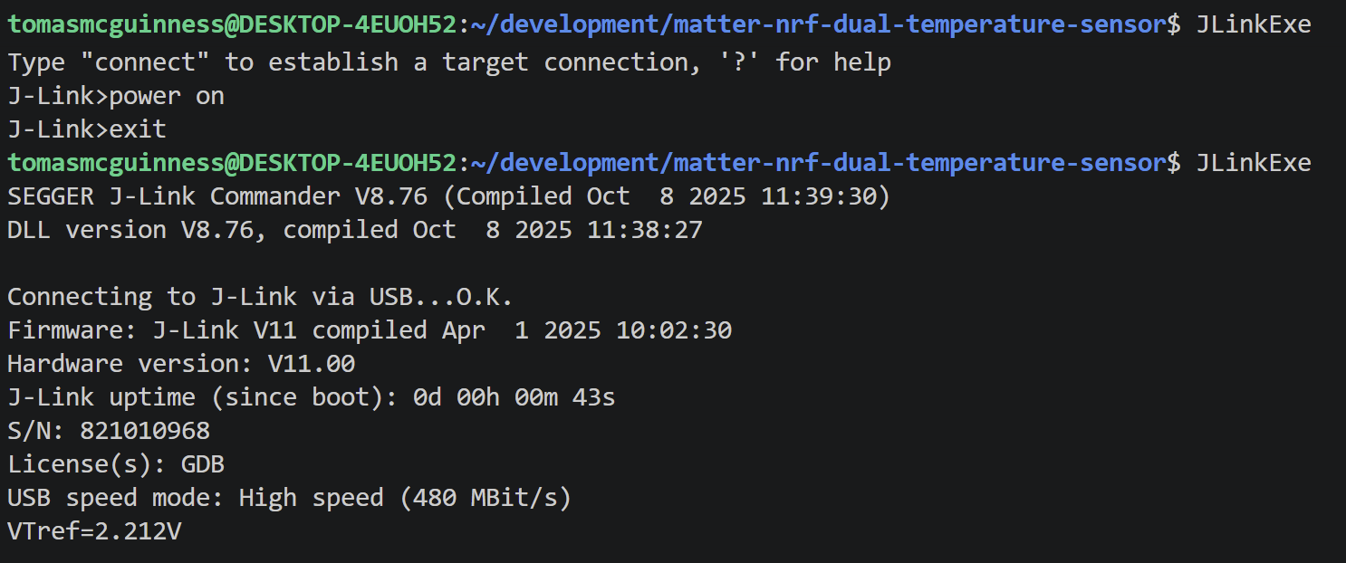
With my board connected, I powered it up using the JLinkExe. This applies 5V to the board.
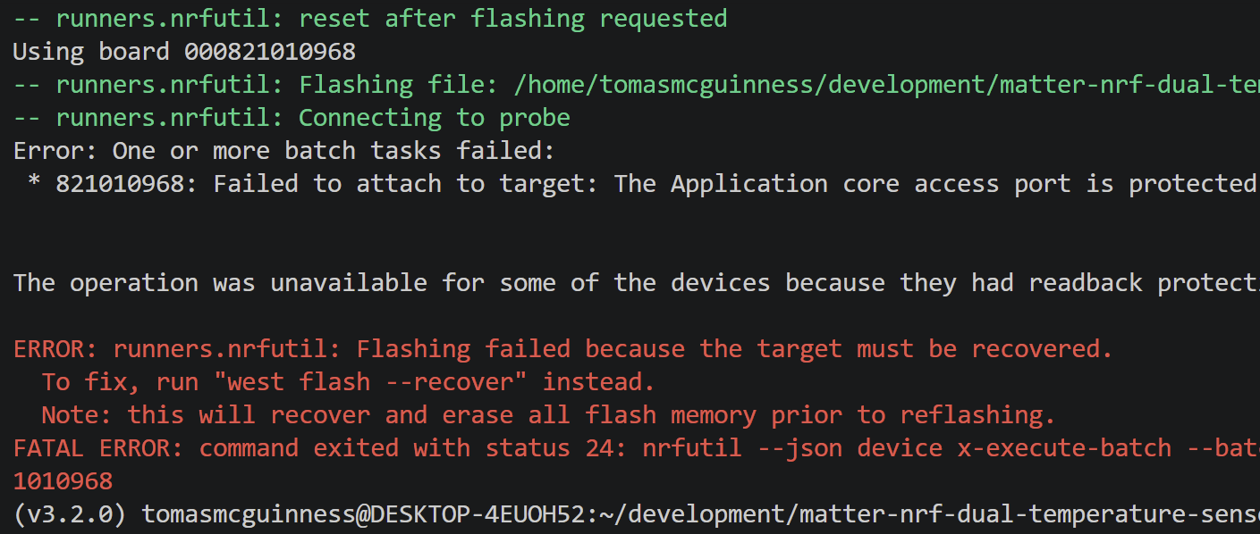
I then tried to flash my dual temperature sensor code onto the board.
This failed initially due to write protection, which was a very good sign!
I then realised I was in the wrong project directory!
I compiled the right firmware
west build -b nrf54l15dk/nrf54l15/cpuapp
and then ran the suggested command
west flash --recover
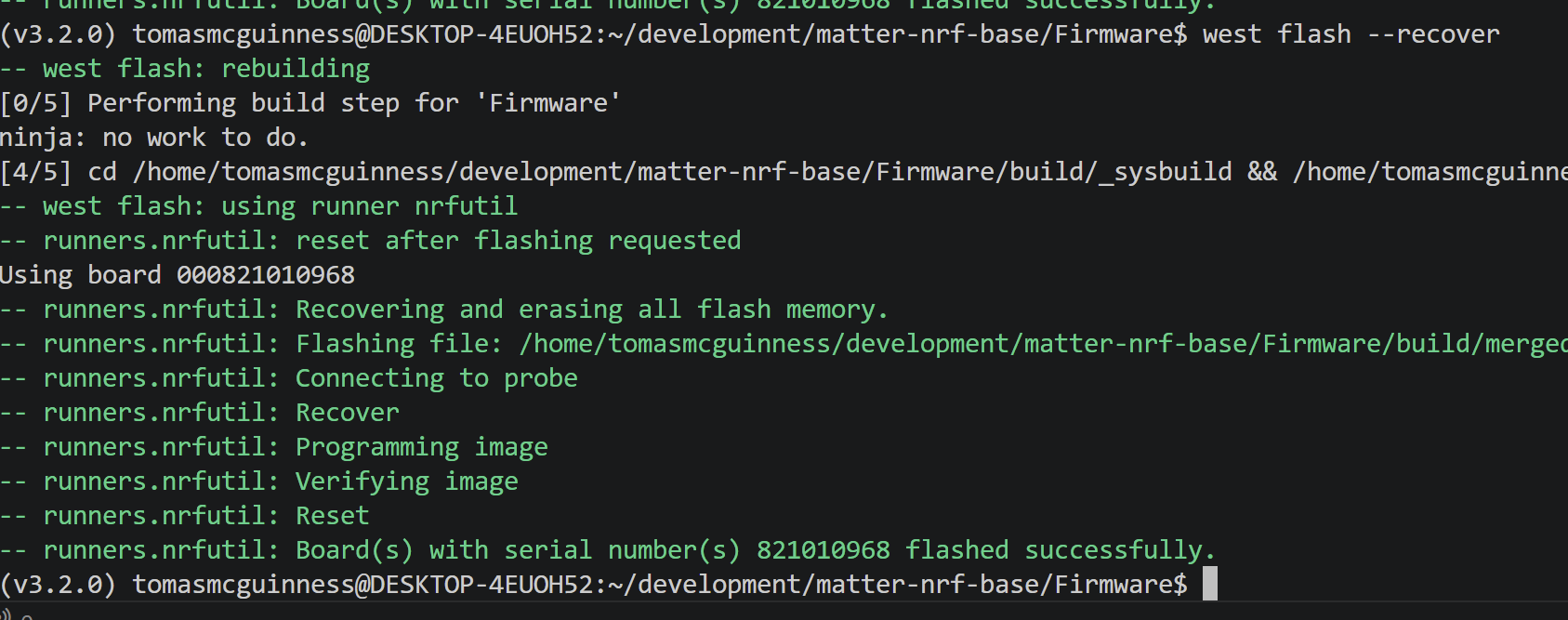
After a second, the LEDs began to blink!
Success!
Summary
I’m feeling pretty good that this worked first time!
I plan on using this board to help me explore more Matter projects, like switches and displays. The board includes a header for all the available GPIOs, so I should have access to everything the module has to offer. It’s also smaller than the devkits and with the integrated battery holder, allows more flexible locations.
I have a one immediate thought for the next revision and that is a header to let me measure current, so I can assess power consumption. A small tweak, but one that would help me optimise battery life. But I guess that is what the real devkit is for 🙂
If you want to try this yourself, the PCB and sample firmware are on Github: https://github.com/tomasmcguinness/matter-nrf-base
If you have any questions, please use the comments or get in touch via social media!
Did you enjoy this post?
If you found this blog post useful and want to say thanks, you’re welcome to buy me a coffee. Better yet, why not subscribe to my Patreon so I can continue making, tinkering and sharing.
Be sure to check out my YouTube Channel too – https://youtube.com/tomasmcguinness
Thanks,
Tom!

Leave a comment