As we’re now (almost) back into the heating season here in the UK, I thought it would be worth posting a brief update on my radiator sensors project!
The aim of this project is to develop a set of sensors that connect to the flow and return pipes of a radiator (the tails) for the purpose of balancing and *eventually* controlling the output of each radiator
I start work on this back in 2023, but once the mild weather arrived in 2024, I had to put everything back in a box as it’s hard to justify keeping the boiler burning!
Where I got to
I made a lot of progress over last Winter and by the end of the heating season, I had sensors deployed across my whole house, monitoring each of the ten radiators in my house.
Each sensor broadcast its readings across a Bluetooth Mesh to a central unit.
The Sensors
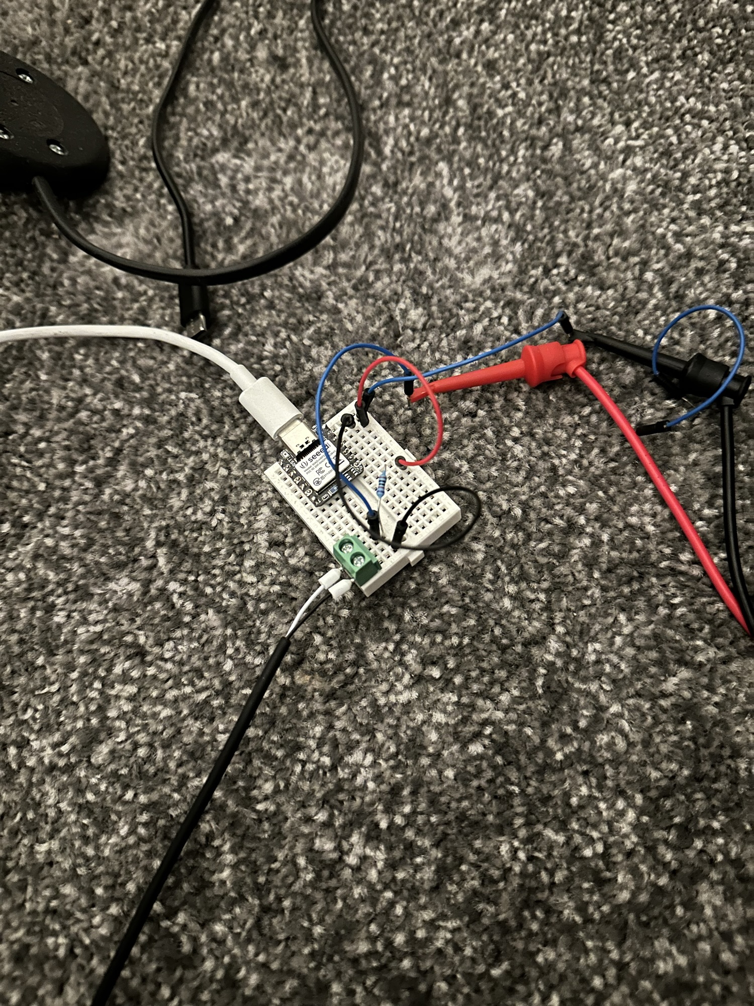
I had a few sample PCBs printed and used two of those with the other eight being on breadboards. I even experimented with battery powered units.
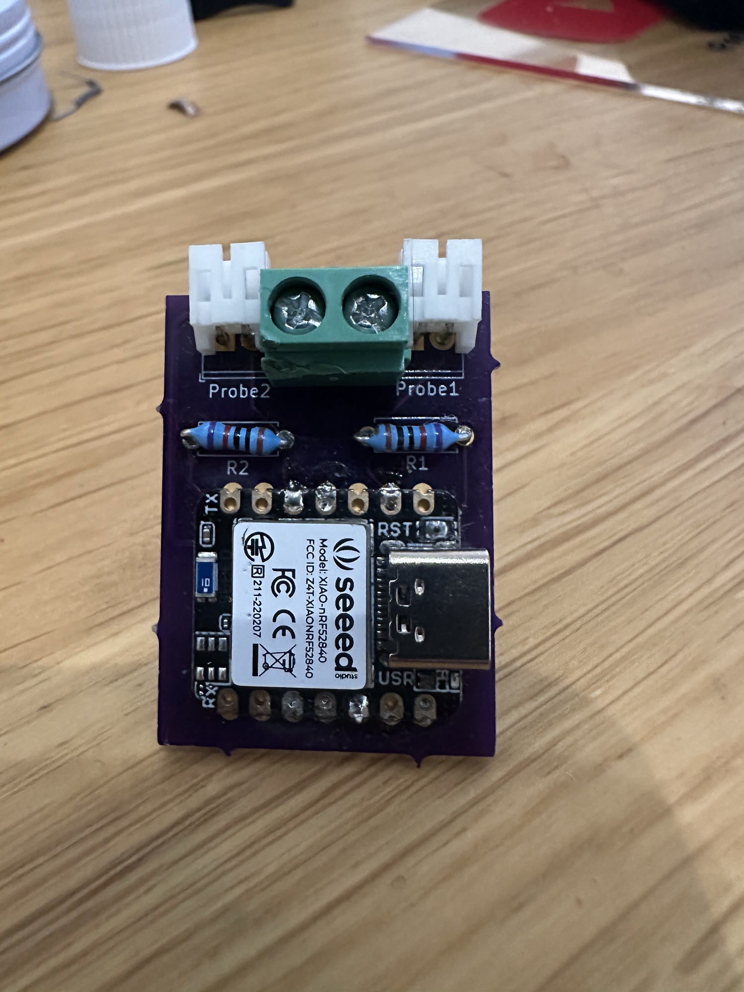
I had lots to learn about Bluetooth Mesh and different temperature sensors types! I had started with digital sensors (DS18B20), but ended up using NTCs as I found they responded better. I also picked up special sensors that could be fixed to pipes.
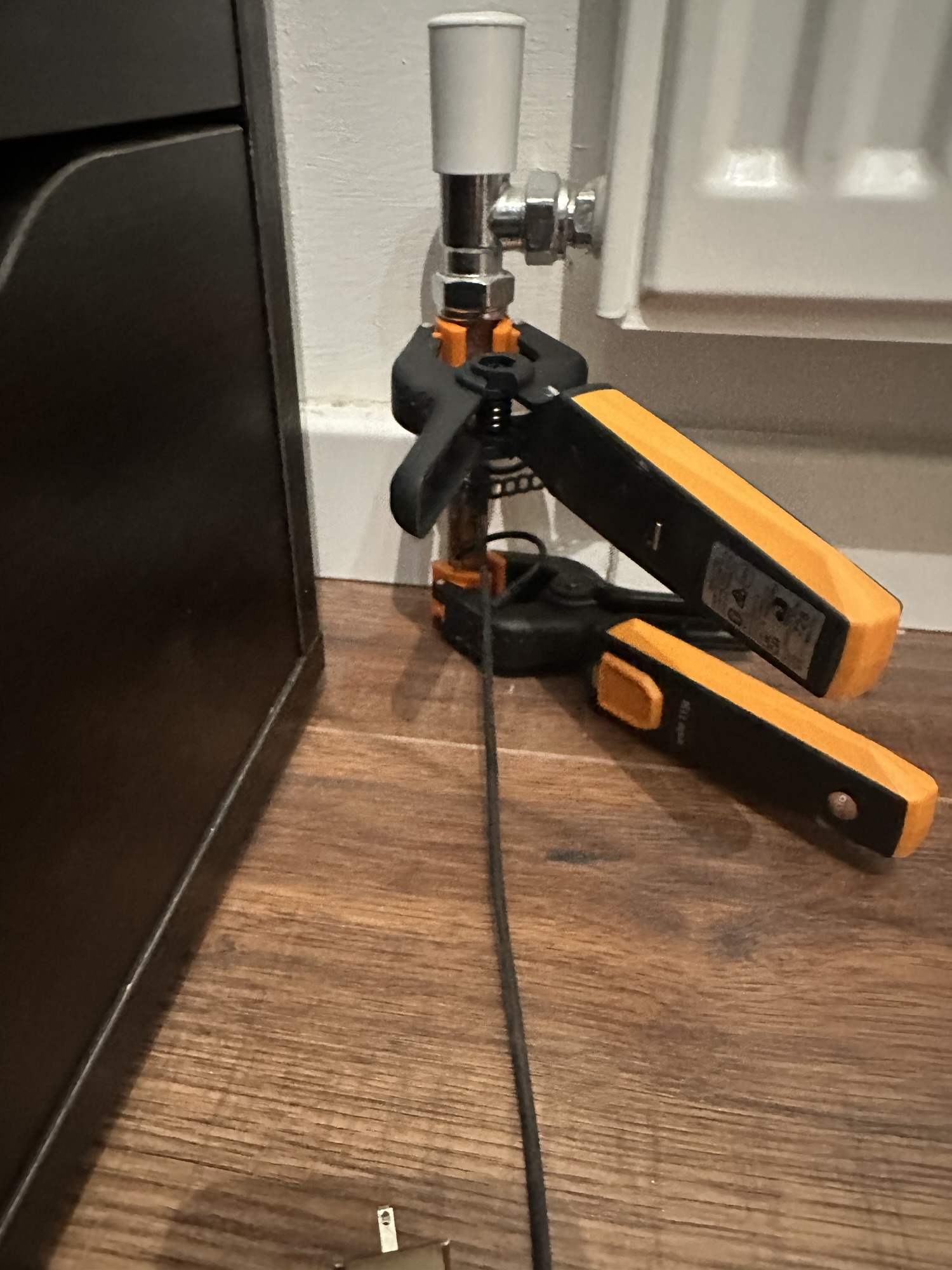
After a lot of experimentation, I got my units pretty close to the reasons from my professional Testo clamps by using high quality resistors and thermal paste!
The Bridge
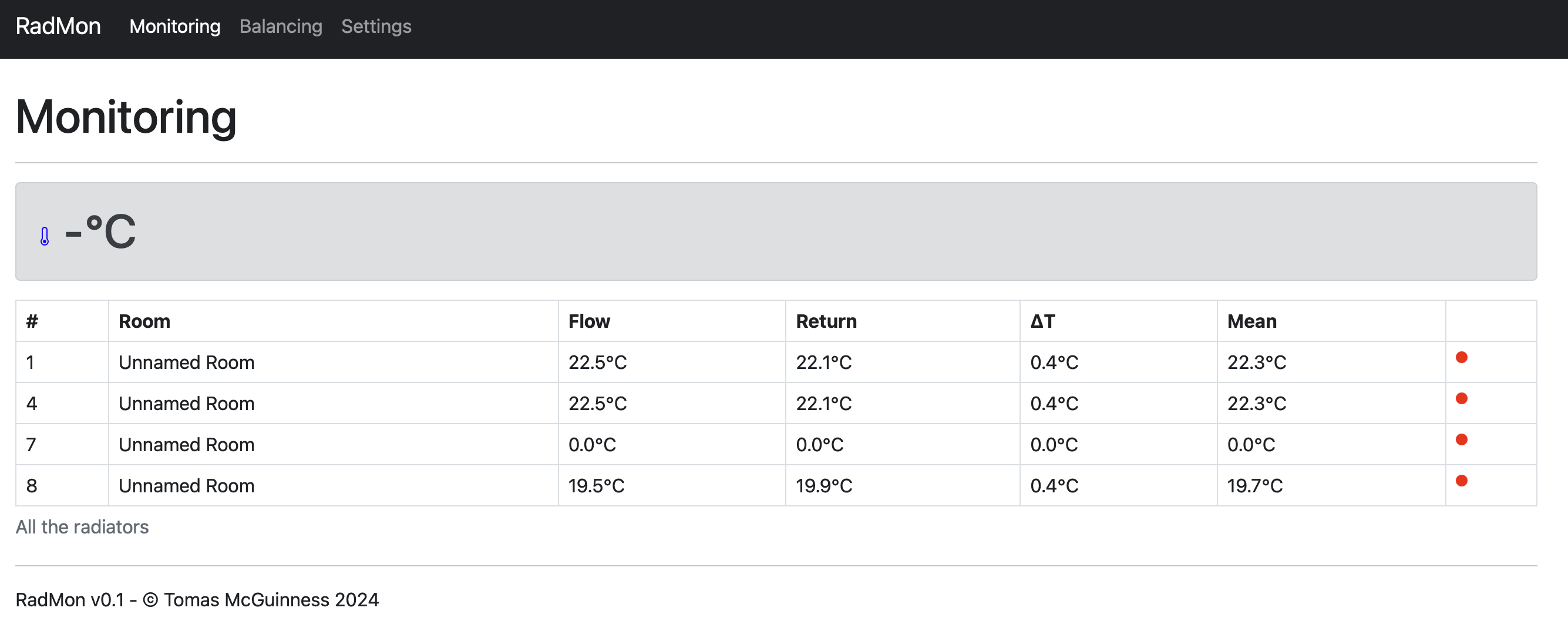
The bridge started as simply something to send the readings harvested from the sensors to an MQTT server, but the more I experimented, the more I realised it would be useful if it could be standalone, so I developed a web interface for it.
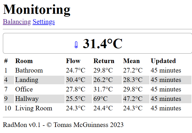
This was enormously helpful when it came to getting all ten sensors online!
I even made progress with the balancing, but by now, the weather had started to warm.
Picking up where I left off!
As we came into September 2024, I dusted off the box and took all my sensors out to ensure they all still worked!
My first priority was to try and get some more PCBs printed and to use some proper connectors on the NTCs, rather than the screw terminals I was using.
I found a company in Germany that worked with KiCAD (which is how my PCBs were designed) so I had them print 6 units. These would be in addition to the three I had, with my office remaining on a breadboard for each experimentation.
The company is Aisler. I had the first few boards printed in the USA, but whilst the boards were cheap, the postage was mental. Aisler was a little more expensive per board, but the postage was much cheaper (and quicker!)
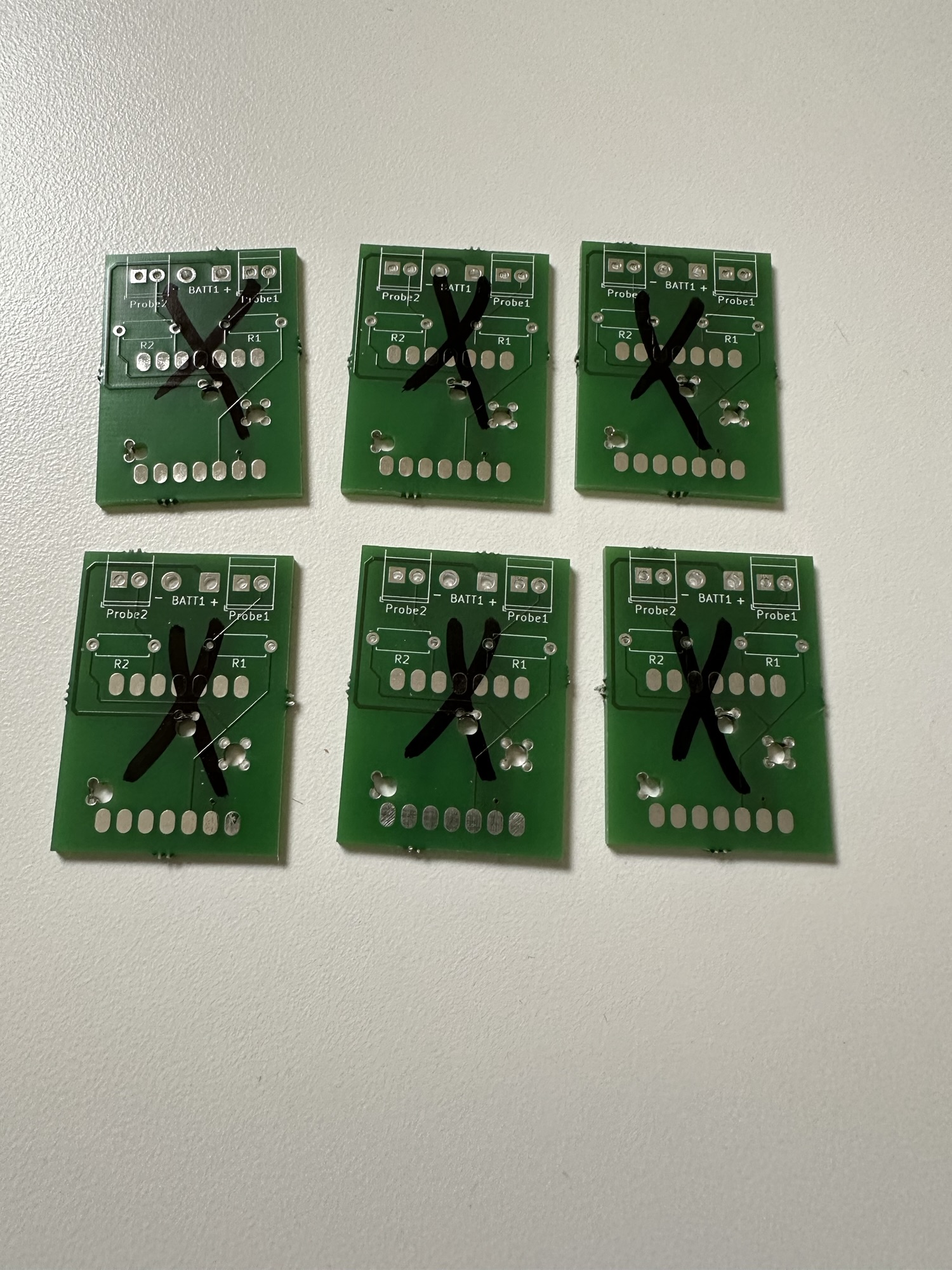
Unfortunately, each board had failed a quality check and were marked with a black x. Thankfully, the issue only affected the battery terminal and since I was planning on using the USB connection, it didn’t matter. Some rubbing alcohol removed the x and I was good to go!
For the NTC, I wanted to terminate them with JWT connectors and after a lot of attempts, I managed to successfully terminate one of the sensors!

I need a lot of practice, but this is much tidier. They are easier to remove now, without needing a screwdriver!
Lastly, I gave the Bridge software a makeover using Bootstrap.
What’s next?
My goal for October is to solder up all the sensors onto the PCBs and crimp the remaining 19 NTC sensors. Then I can reattach them to the radiators without them looking completely terrible.
Once reattached, I want to give the balancing a go and see if that can improve the performance of some of the radiators in my house.
If you want to know more, I have made a series of YouTube videos and you can check them out here https://www.youtube.com/playlist?list=PLJbTlpVEb1GBlkOyDTDww-0ecKl7urweg
If you have any questions, please ask in the comments!

Leave a comment