
As I get closer to finishing v0.1 of my Zigbee F.A.R.T. sensor, I continue to look at power consumption. This is my first post of 2025, so Happy New Year!
I thought I was doing okay!
My initial testing had the sensor sipping an average 400µA. Some more tinkering got that down to around 300µA. I felt that was pretty good as it meant a battery life of ≃ 280 days. Well over my six months target, but it was higher than I expected.
After a chat with Peter Eastern on BlueSky, he suggested that my voltage divider arrangement would be consuming power. A quick calculation showed that the pair of them would use 330µA.
When you apply a voltage over the divider, current will flow. My divider is made up of a 10kΩ resistor and a variable NTC thermistor. For simplicity, let’s assume the NTC is at 10kΩ too. That gives a total of 20kΩ resistance and a potential of 3.3v. Using Ohm’s law, this gives a current of 165µA. We have two dividers, yielding the 330µA.
Would this explain the high consumption figure when the nRF52840 was supposed to be asleep?
The importance of correct testing
I decided to check the consumption of the dividers. When I sat down at my desk to check, I had a horrible realisation! I was measuring the consumption of the Seeed XIAO nRF52840 board by itself.
When testing the code I was using a simple potentiometer divider. But when testing power consumption, I was only testing the chip on its own!
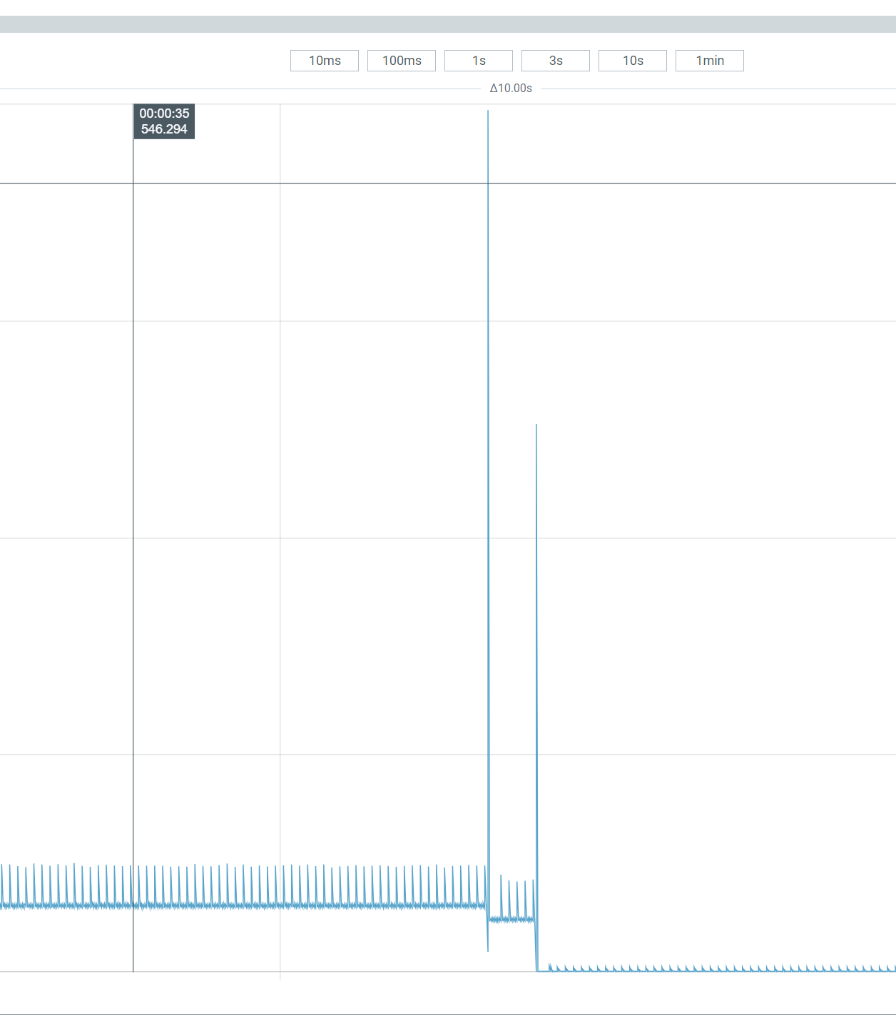
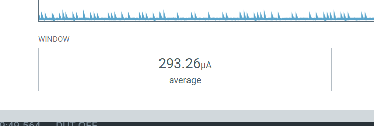
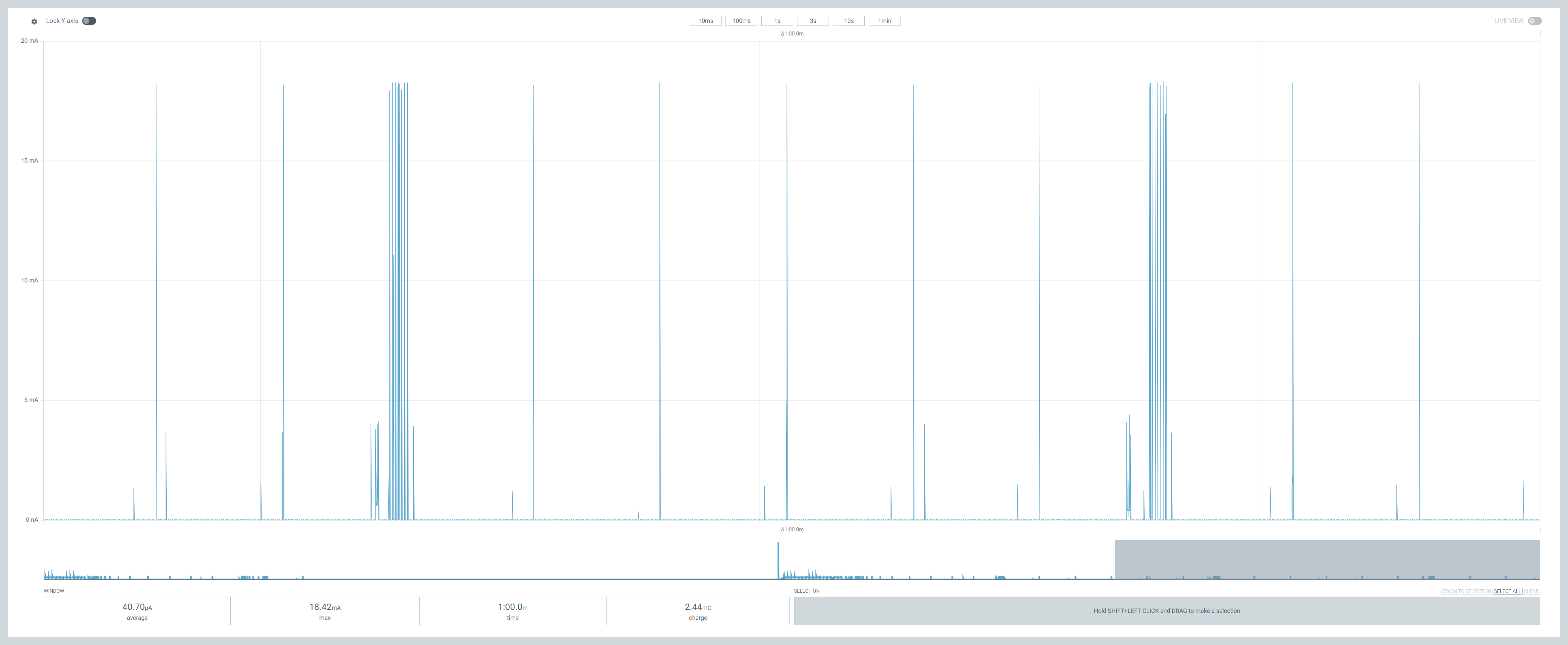
Running the consumption test again, with the simple divider circuit attached, more than *doubled* the consumption! It rose from an average of around 300µA to well over 600µA!
Here you can see the before and after. Not good!!
This confirmed Peter’s assessment that the voltage dividers were indeed using power. It also meant that my device’s battery life was now only 140 days. Short of my target six months 😦
First things first
I needed to remove the consumption from the voltage dividers to keep the six months of battery life.
Peter suggested I should turn off the power to the dividers when they weren’t being used. This would eliminate the constant current flowing across the dividers, lowering their average consumption.
I needed to turn on the power to the dividers, take some measurements using the ADC (analog-to-digital converter) and then turn it off. This seemed like a job for one of the GPIOs.
Based on the layout of my PCB, one of the pins on the left would be perfect.
I was using P0.03 (A1) and P0.04 (A4) to take ADC readings already. This made P0.28 and P0.29 ideal candidates. To clean up the PCB layout, I moved the 2nd ADC to P0.29 and configured P0.28 as power.
The reading thread would then toggle the power on and off.
// Switch on the power pin.//int err = gpio_pin_set_dt(÷r_power, 1);// Let the voltage stabalise.//k_sleep(K_MSEC(100));uint16_t temperature_1 = read(0);uint16_t temperature_2 = read(1);// Switch off the power pin.//gpio_pin_set_dt(÷r_power, 0);
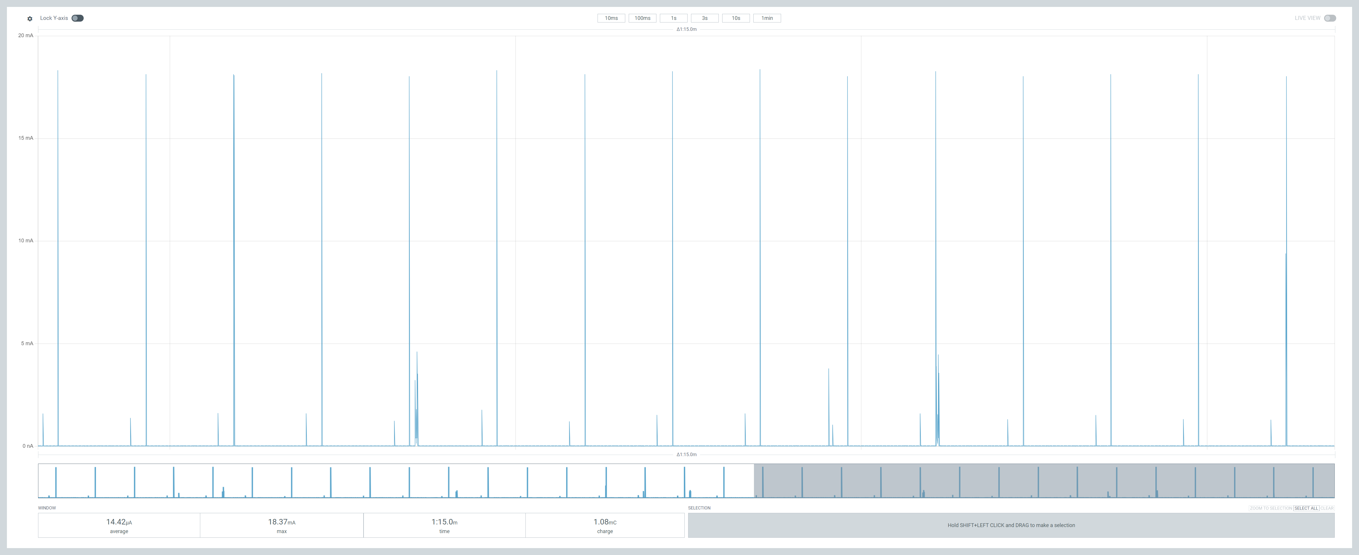
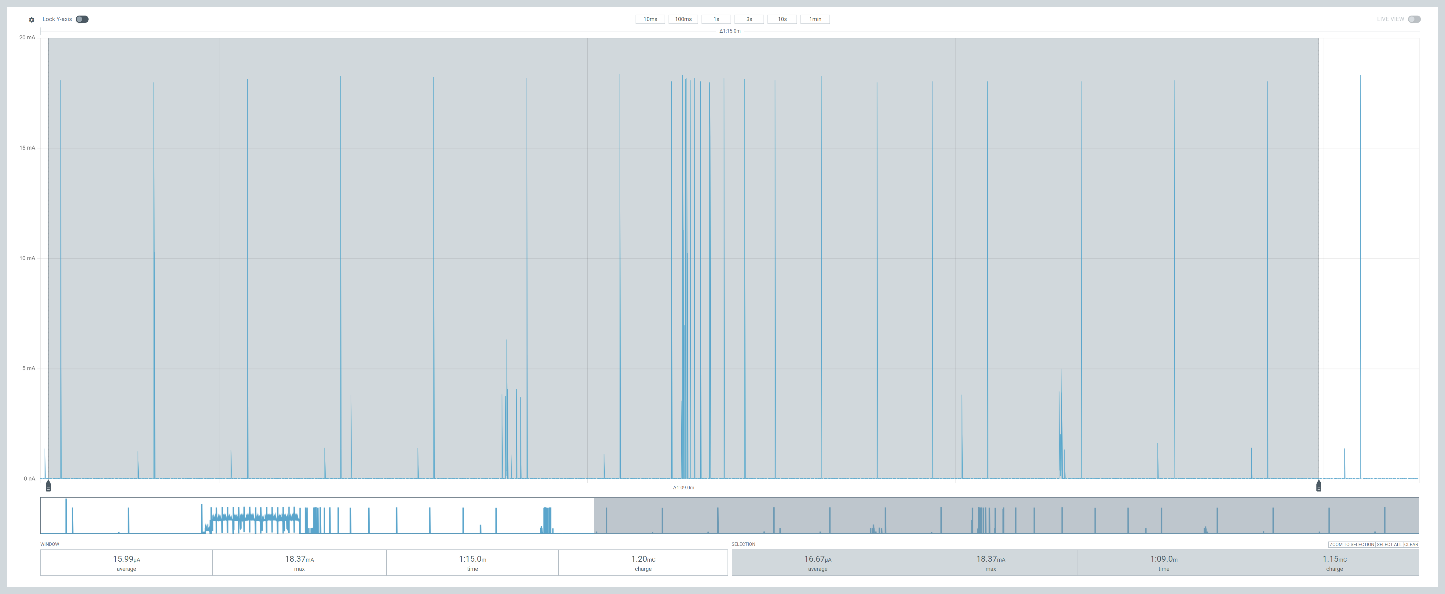
This worked well and since the GPIO output was nicely regulated, I got a nice resistance reading!
This now meant the 300µA drawn from the voltage divider was short lived.
I decided to see what else I could trim off the remaining 300µA average consumption.
Finding that extra power usage!
I began this investigation I decided to see what the power consumption was like when the chip was doing nothing. If an idle chip was still drawing 300µA, I’d have no hope!
From what I had read, the nRF52840 had two sleep modes, “System On” and “System Off”. The former being a light sleep and the latter being a deep sleep.
“System Off” is when the chip is completely switched off. I knew this wasn’t for me as the Zigbee threads would be waking up to ping. This would mean the chip rebooting a lot.
“System On” puts the chip to sleep, but it’s still awake. From Nordics documentation, even “System On” requires only a few µA. It’s also a mode the chip enters automatically when it senses it’s doing nothing.
I replaced the main() method with this basic block of code. When the main thread when to sleep, the chip should put itself into “System On” as the thread is idle.
int main(void){ LOG_INF("Starting Zigbee FART Sensor"); while (1) { k_sleep(K_FOREVER); }}
Running this simple code still yielded an average of 261µA!!
From Nordic’s own power guide, if the CPU is idle and you’re seeing 100s of µA, then it’s a peripheral. I wasn’t even sure at this point that the CPU was inactive! Was k_sleep(K_FOREVER) enough to put the chip to sleep??
I decided I need to start at the bottom and try and build up an understanding of what is happening. Thankfully, as ever, somebody else had done it!
https://forum.seeedstudio.com/t/low-power-with-xiao-nrf52840-on-zephyr-rtos/270491
I pulled down the code and tried to compile it, but the method pm_state_force caused the compilation to fail. I resolved that by replacing it with a call to sys_poweroff.
Running it gave me very surprising results! When I put the unit into SYSTEM OFF, the consumption was tiny at 2.3µA!

Pressing the “do work” button (which lights the blue LED) saw consumption rise to around 300µA. When I toggled off the LED the power consumption dropped to 3.9µA!
The “system off” and “idle” consumption figures are higher than the blog post, but we’re talking 1 or 2µA. That’s probably manufacturing tolerance at this stage.
I now knew the XIAO nRF52840 *could* run down in the single micro amps. Armed with that, I was sure I reduce my Zigbee consumption further!
One of the comments I spotted whilst reading the sample was this:
Prevent deep sleep (system off) from being entered on long timeouts or `K_FOREVER` due to the default residency policy.
I wondered if this explained why my Zigbee sensors dropped offline after indeterminate period of time? My code does use K_FOREVER. Something to return to 🙂
Fixing the power consumption
I started with the overlay. I hadn’t turned off all the SPI peripherals, so I added those.
I took out my ADC configuration too.
This made no real difference
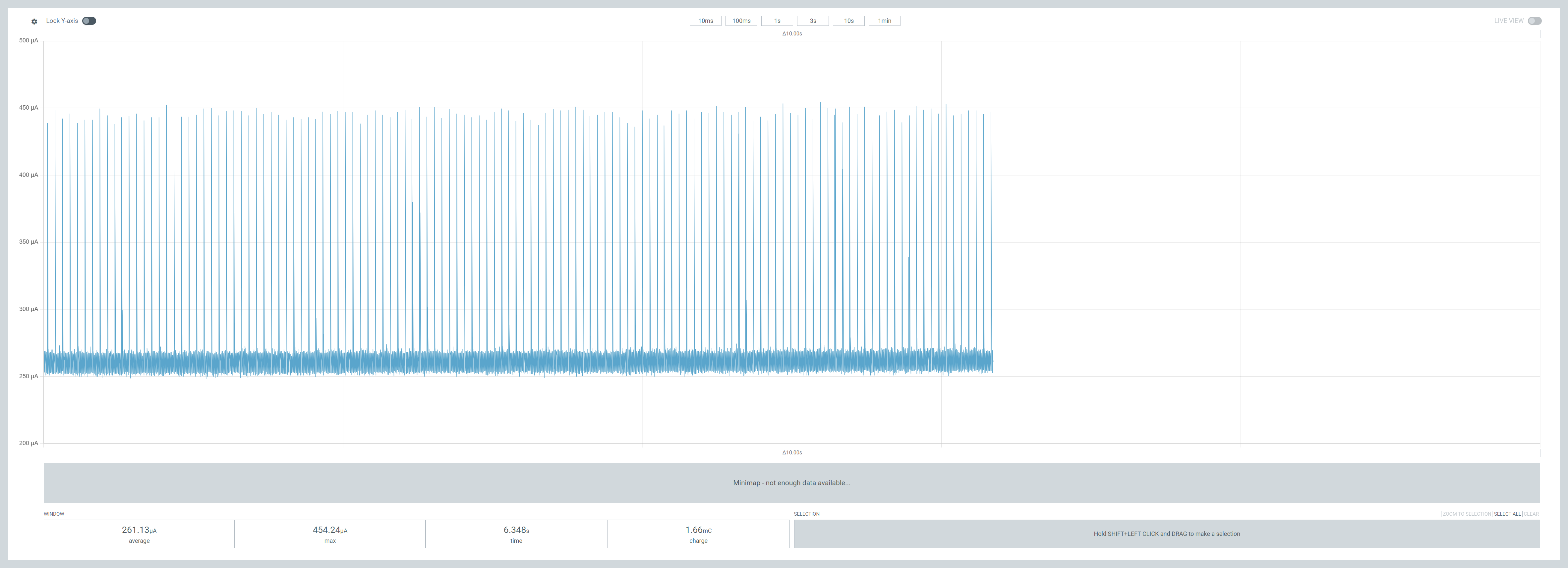
Next, I looked to the QSPI flash code. I’m not 100% sure what this is all about, but the code in the sample was turning it off. I copied in the code and bingo! Power consumption plummeted!!
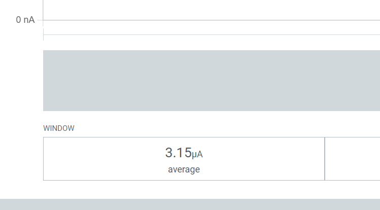
With the empty block using no power, I turned back on my ADC code. This takes a reading from two ADC pins every thirty seconds. Amazingly, the consumption averaged 3.26µA over two minutes and the ADC spikes can be seen every 30 seconds!
Very promising!
Of course, taking ADC readings is no use with the Zigbee code to send them……
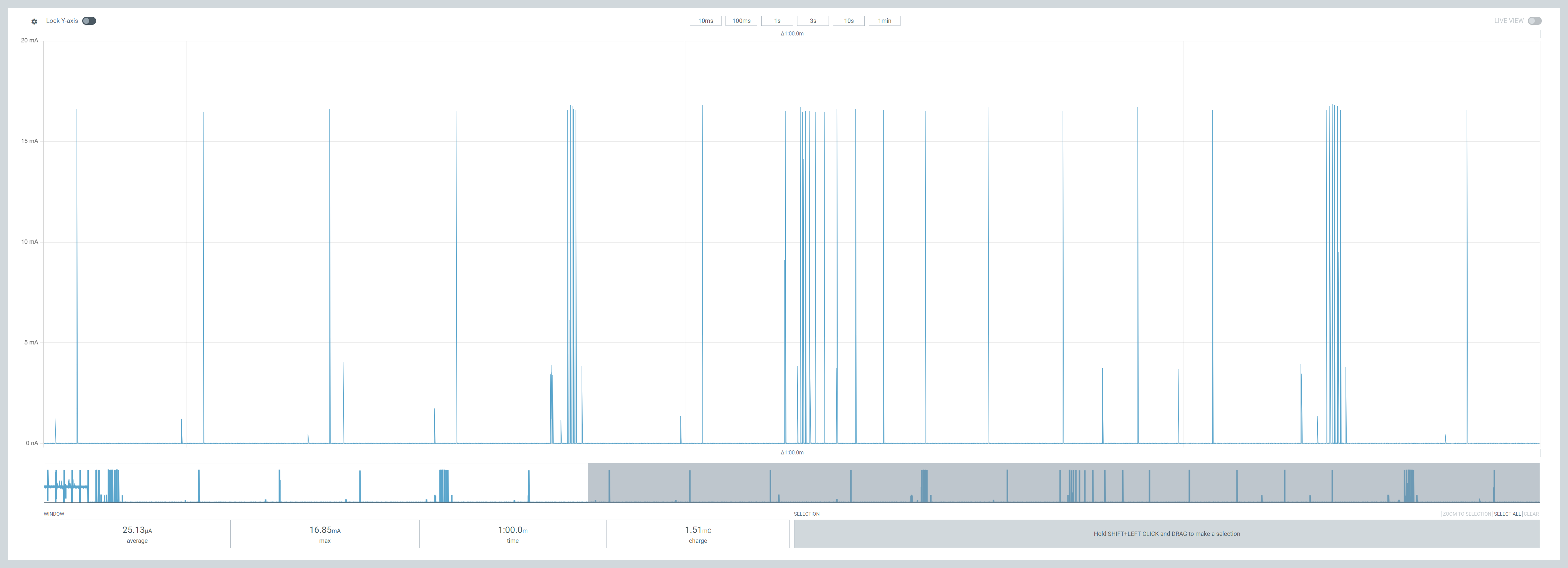
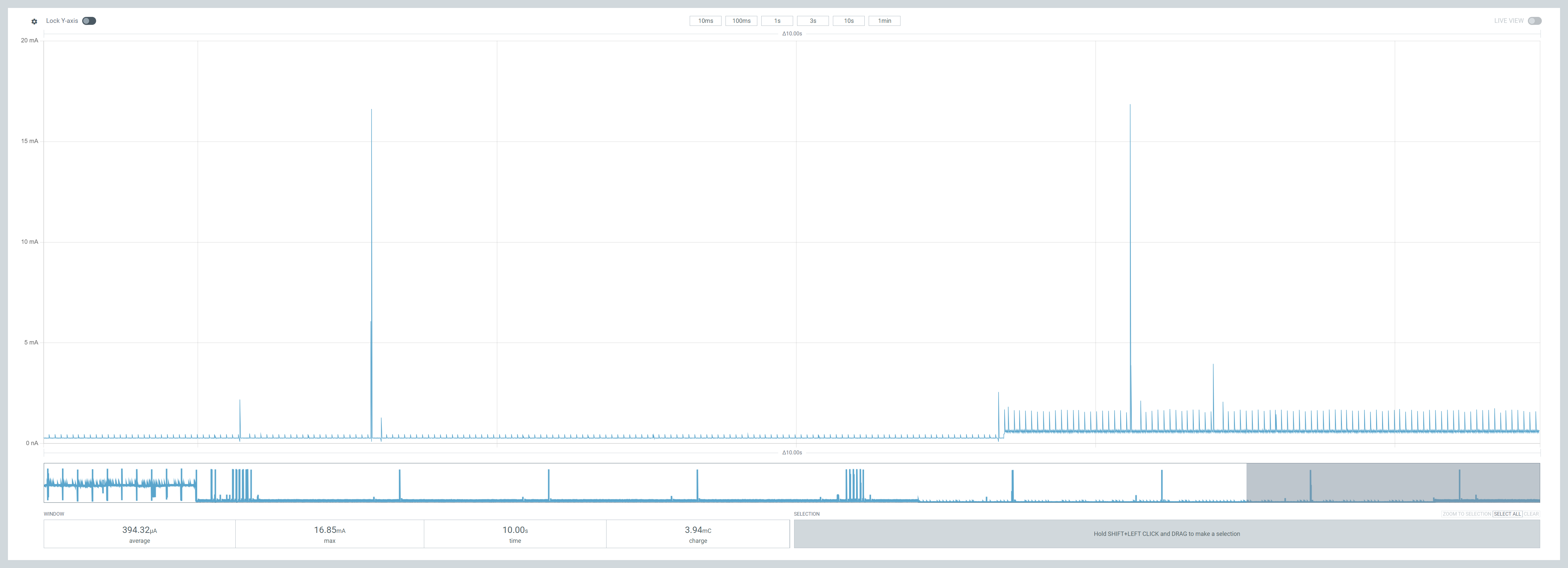
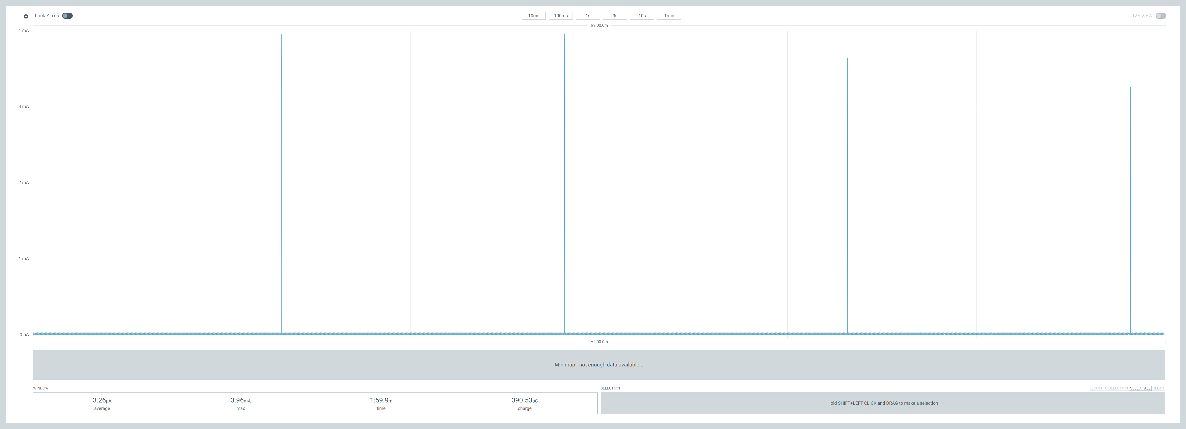
Speechless! Only 25µA! The Zigbee radio is working as I can see the massive 15mA spikes. Home Assistant also reported the sensor checking in!

Final results
I let the sensor run over the course of a minute, and the consumption was at 22µA, which is amazing.
But when I came to connecting the device to Home Assistant, the interview just wouldn’t complete 😦
When this happens, the advice is always “check for interference”, meaning the problem is radio based.
I thought of this line I copied from the power sample
nrf_802154_tx_power_set(8);
This lowers the power of the radio to reduce consumption. Too low it seems to allow HA to configure it. I have Zigbee light bulbs in my office light, so the coverage should be very good. But the power of 8 is obviously just too low. I commented out that line and sure enough, I paired the device successfully.

As expected, this raised the average consumption over one minute to 40µA.
Don’t get me wrong, I’m really happy with 40µA, as it’s a far cry from the 600µA I started with. The 40µA would be 240 days on a coin battery, but a whopping 5 years on a 2000mAh one!
I’m sure there is room to reduce the power consumption by tinkering with the TX power. This is software based, so I’m not too concerned about it now. When I did this testing the MCU was in a nest of wires on a breadboard, which probably didn’t help.
One observation is that the measured temperature is only 24.0°C. It should be much closer to 25 as I’ve balanced the Potentiometer. Feels like the value was being rounded. Another item for the glitch list 🙂
Next Steps
I’ve paused my PCB order with Aisler.net to and I’ll refine the track layout to facilitate the change in pins. Once I get the new boards, I’ll experiment a little more with the TX power.
This is a good start to 2025 🙂
Update!
I came back up to record a quick short/TikTok and spun up the PPK recorder again.
The sensor’s average consumption is actually being recorded as 15µA!
The number I look at in the bottom left is the *total* average since recording began. My recordings always included the initial Zigbee bootup and network negotiation.

Whilst low at an average of 7mA, that’s *massive* compared to the 15µA or 20µA. If take an average *after* the Zigbee code has settled down, we’re actually only using 16µA.
This is even better news!!!!
At that consumption, we’re talking 1.5 years on a coin battery or an eye water 15 years on a 2000mAh battery.
This is *with* the unchanged TX power too! Amazing.
I’m not going to look at this again, save it goes back up 🙂
Did you like reading this post?
If you found this blog post useful and want to say thanks, you’re welcome to buy me a coffee. Better yet, why not subscribe to my Patreon so I can continue making tinkering and sharing.
Be sure to check out my YouTube Channel too – https://youtube.com/tomasmcguinness
Thanks, Tom!

Leave a comment