When designing the PCB for my F.A.R.T. sensor, I had to decide which way the +/- terminals went.
I had some wired connectors, which looked like this:
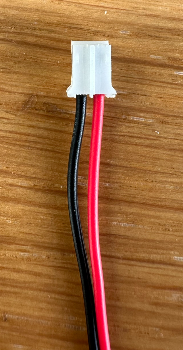
I designed my PCB with this orientation of positive and negative and thought no more of it.
However, when I tried to connect a LiPO battery to my sensor I realised something was amiss! Here is the connector from a 2000mAh LiPO battery:

The keen eyed amongst you will spot the problem.
What’s the right way?
If you haven’t spotted the issue, that’s okay. I didn’t see it at first either 🙂
The positive and negative terminals are the opposite way around!
One of my followers on BSky (@rmappleby.bsky.social) pointed me to this post on sparkfun:
https://learn.sparkfun.com/tutorials/single-cell-lipo-battery-care#jst-ph-connectors
They refer to positive/left, negative/right as the “standard” way adopted on their batteries.
I’ll be making a change to my PCB battery terminal to mirror sparkfun’s recommendation.

Leave a comment