I recently published a video to my YouTube channel about Kinetic Switches.
Kinetic switches are ones that don’t have a battery. Rather they use the energy generated during the push to send radio signals.
Before December, 2024, I didn’t know they were even a thing.
In my video, I look at an Ener-J Kinetic Switch and Macguyer a solution to connect it to Home Assistant. Basically, I use a Shelly i3 to listen to the Wireless Receiver, detecting changes in the relay (open or close).
Whilst this works, it’s hardly ideal.
These Kinetic Switches are expensive enough as each one requires a receiver. My solution adds the need for Shelly i3 into the mix. The Shelly i3 can monitor three of them at a time, but I would still need a relay per switch.
Somebody on Reddit mentioned a project that uses an SDR (software defined radio) to generate MQTT signals for kinetic switches. The also confirmed that the Ener-J products used a wireless frequency of 433MHz.
This was a clever idea as it took the relay out of the picture. For me, that would also eliminate the need for the Shelly.
Listening for 433MHz signals
Whilst I didn’t have an SDR, I had a 433MHz radio module lying around i.e. I got it for another project I never even started!
The module in question was the D-SUN CC1101 breakout board.

I decided to try and use this to pick up the signals from my Ener-J switches.
Where to start??
After a very intensive hour on Google, look for code, I came across this project: https://github.com/nopnop2002/esp-idf-cc1101
This looked like what I needed. It connected a CC1101 to an ESP32 and displayed the received data.
I immediately connected up the breakout board with an ESP32-H2. I used the ESP32-H2 as it happened to be connected to my PC at the time (for a Matter protocol project)
The board itself is a Waveshare ESP-H2-DEV-KIT-N4 if you’re interested.
After a little tweak to the “basic” sample, it fired up!

Clicking the Grid switch
With the radio connected, I clicked my grid switch and, rather naively, expected the signal to be displayed.
Nothing happened because nothing is that simple!
Thankfully, somebody else on Reddit had posted a link to a YouTube video, which seemed like it would answer my questions!
In this video, Cameron Gray takes us through how he made a custom receiver for his Quintec kinetic switches!
Exactly what I was after!!
He explains in great detail how the code works (for an Arduino). He then started to explain roughly *how* he reversed the radio pulse. Turns out the CC1101 needs a lot of configuration to work correctly. Who knew 🤣
You need to provide the CC1101 with things like frequency range, bit-rate and something called Sync Words. Without these parameters, it doesn’t know what it’s listening for.
I copied some of his values Cameron used in his video, but that didn’t help. I didn’t expect it would since the brand I’m using is different.
If I wanted to repeat his steps for my Ener-J switches, I needed an SDR. I’d wanted one of them for a long time, so I ordered one. I chose the same one that Cameron used in his video; a Nooelec Smart V5.
That’s January’s YouTube revenue put to good use!
The SDR!
After waiting patiently for a few days, the SDR arrived. I eagerly plugged it in and tried to get it working. To “see” what an SDR is picking up, you need to use some software.
I initially looked at the CubicSDR software, same as Cameron, but the last build was from 2018!
Nooelec mentioned that SDR++ was another supported piece of software and that was last build in 2022. Being much newer, I loaded that onto PC and fired it up.
After tinkered for a few minutes, I could see radio noise!

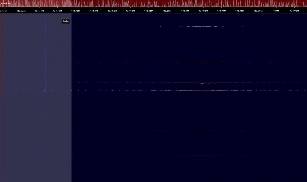
After I figured out how to adjust the frequency, I tuned into BBC Radio 1 and 2. I then moved to 433MHz and I was able to observe the clicks from the kinetic switch!
The little horizontal lines show the pulses.
The next piece of software used by Cameron was Universal Radio Hacker. This was last updated in November 2024, so the project was more actively maintained!
I launched this and used the spectrum analyser to find where the signal was.
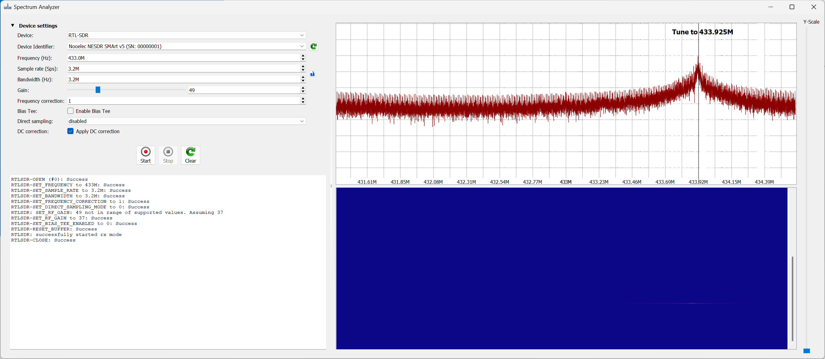
Clicking the kinetic button resulted in a spike at 433.925MHz.
Knowing where the spike was let me move to the next step: recording the signal. That’s done using the Record Signal feature.

I didn’t adjust anything and simply clicked the Kinetic Switch. For good measure, I clicked the second one too.

Just like Cameron, I observed two spikes when I clicked the kinetic switch. The first is when I push the button and the second is when I release it.
So far, so good!!
Once I saved the recording, URH showed me the pulses in analog. The data seems to be repeated twice, so like Cameron’s switch it repeats itself.

It even displayed a binary value!

Decoding the Binary
This part proved to be *way* more difficult than I expected.
After following the YouTube video, I got nowhere.
Nothing looked coherent.
URH also kept indicating that the protocol was ASK, not FSK.
ASK and FSK are types of modulation. This is how the radio essentially encodes binary into the radio wave.
I don’t know or understand the exact details, but FSK uses multiple frequencies, typically two, to modulate the signal. If you look back at my Spectrum Capture, there really only seemed to be one spike at 433.92MHz.
ASK uses a single frequency, adjusting amplitude (strength) to encode the signal.
I posted the analog trace on X, Bluesky and Reddit. I even ran it through DeepSeek. All of the replies said it was ASK modulation.
Being a novice, I trusted that the Ener-J datasheet was correct when it said FSK and pressed on.
I then found another detailed guide which I tried to follow.
https://secfault-security.com/blog/kineticswitches.html
After a few hours of experimenting, I hadn’t made any real headway. Maybe the device really was ASK? I went back to the internet and came across this ASK decoding guide.
https://olof-astrand.medium.com/hacking-wireless-sockets-like-a-noob-b57d4b4812d5
During that process, URH displayed this as the payload

The pattern of ee88ee88 that was seen reminded me of a similar pattern I had seen during my own testing!

A different way to decode the binary!
I had always just assumed that the ones and zeros I was seeing could be interpreted directly! I was not thinking that maybe this wasn’t the case!
Looking at the click data, we get two separate packets.
1000100010001000111011101000100011101000111011101000100010001110111010001000111011101000111010001110100010001
1000100010001000111011101000100011101000111011101000100010001110111010001000111011101000111010001110100010001
There are repeating blocks of 1000 and 1110. Perhaps these represent 0 and 1?
After fiddling around with URH, I was able to work out how to add a decoding. This just replaces 1000 with 0 and 1110 with 1. Applying that yielded:

This looked a lot more sensible.
All the pulses start with 0xCB so that might be some form of sync word.
Rows 2 and 3 are generated when button is pushed, repeated. 5 and 6 are the messages generated when the button is released.
You can see that the last two parts are different A8 and 20. Maybe push and release?
Messages 8,9, 12 and 13 are from the second different button. Similar at the start and the end!
At this stage, I think I was making progress. I could see that A8 for push was the same for both buttons and 20 for release was the same!
What was missing now was a way to identify the button that I pushed.
The only one other hex character that changed between button 1 and 2 was at position 5. It was 9 for the first button and C for the second.
Button ID
I obviously had *nothing* to base the Button ID on, but four bits didn’t seem like enough. The odds of a collision would be very high if you have a few of these buttons in your house.
The other samples I’d seen showed the serial number of the button being used. For my two buttons, they had a serial number printed on them.
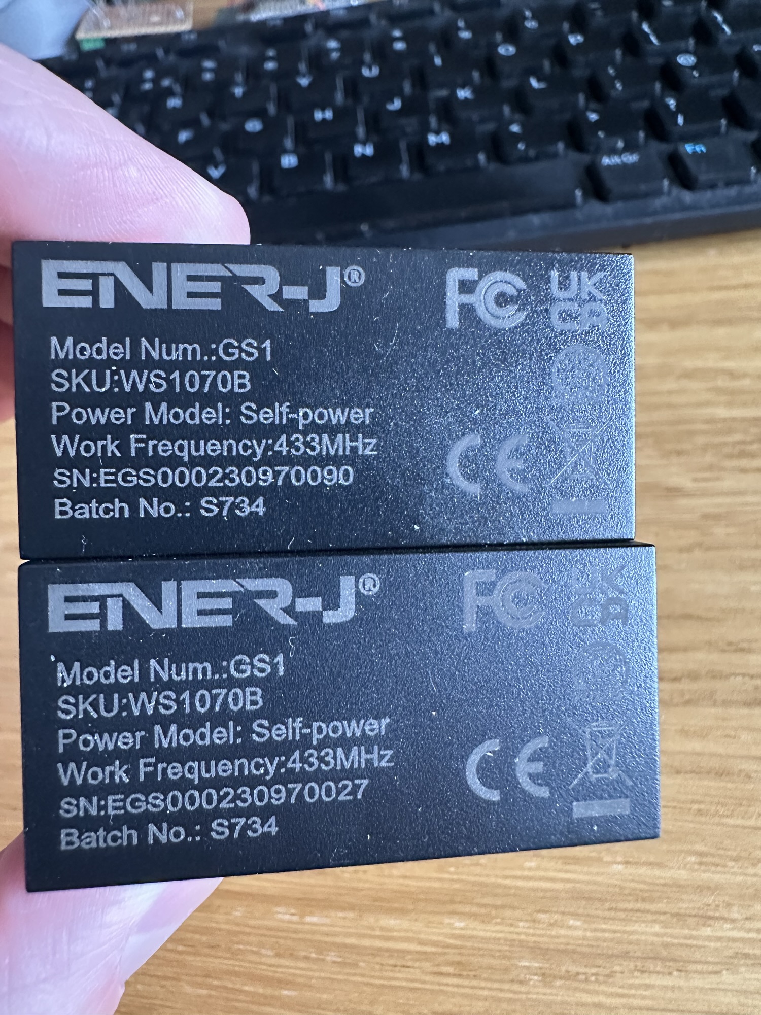
Annoyingly, neither 0090 nor 0027 appeared in either of my little HEX strings. That would have been too neat I suppose!
I didn’t let that deter me thought. I felt I was making some solid progress in decoding the payload!
The only thing that stuck out was the 9 that present in the first few payload messages. 1001 is 9 in binary and it appeared. This didn’t hold for the 2nd set of messages though, so probably a coincidence.
On to the next step!
I think I have got enough now to start trying to detect the signals again. I have the frequency and I think I have the sync word. I’m also confident the modulation is ASK.
This is, I think, enough to try and configure the CC1101 to listen for the payloads. I’ll give that a go and write it up in another post as this one is long enough!

Leave a reply to Sending and decoding a 433MHz signal with an ESP32, a CC1101 and Universal Radio Hacker – @tomasmcguinness Cancel reply