As part of my little idea of a touch-based Matter button, I plan on using a small capacitive button. They are slim and silent. Perfect I thought.
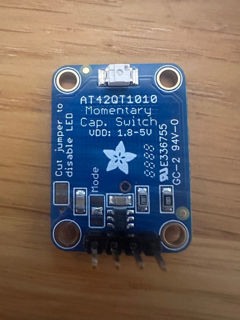
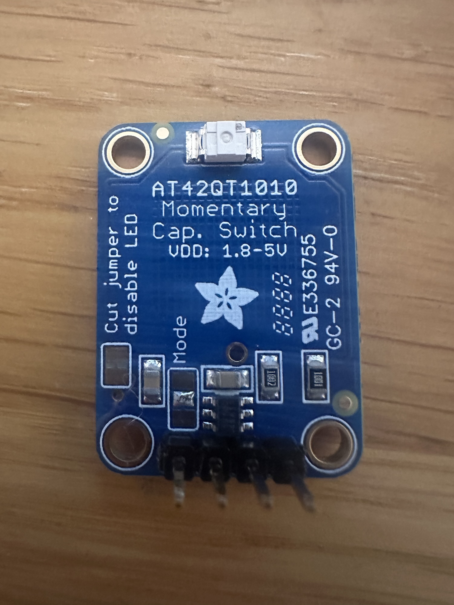
I’m selected an Adafruit AT42Q1010 break out board for this project.
Power Concerns
I’ve been spending my *very* early mornings (before work and before family is up) working on a Zigbee sensor. The goal was a) make it work and b) make it last at least six months on a battery.
This has been a really interesting project. It has shown me that insanely low power consumption is possible. I got my nRF52840 based sensor using an average of 16µA. This gives a potential battery life on a coin battery of 1.5 years! Well past my six-month target.
With this fresh in my mind, my thoughts turned to the capacitive button I planned to use with my ESP32. As it’s always on, the power consumption would need to be very low to make it practical for my project. Armed with my new Nordic Power Profiler Kit, I decided to test it in isolation.
Turns out it’s a hungry little gizmo!
When I bought this break out board, I wasn’t paying any attention to power consumption or anything like that.
I decided to start at the specification:
https://mm.digikey.com/Volume0/opasdata/d220001/medias/docus/5011/1374_Web.pdf
One line jumps out:
If you want to save power, the LED can be disconnected from the output pin (cut
the trace between the jumper marked as such). We designed this breakout to
have the more-responsive “fast mode” which draws about 0.5mA. If you need
ultra-low (~50uA) power usage, the mode jumper can be cut on one side &
soldered closed on the other to fix it into that mode.
It’s either 500µA or 50µA. Quite the difference. On a 2000mAh battery, that’s 166 days vs. 1,666 days. I need my device to use less than 100µA so that the battery life is measured in years, not days.
Hooking it up to the PPKII, shows it uses a little more:

I pressed the button three times, and you can see the spikes. They are high, going a little over 2mA.

Thankfully, the Adafruit board offers a few tweaks that can help reduce the power consumption.
The Jumper and the Mode
On the board, the LED jumper and Mode jumper are both visible. I will cut the jumper to turn off the LED and then use the Mode to select the “Slow” mode.
Starting with the LED, this can be permanently disabled by cutting a copper jumper on the back of the board. That’s easy. Using a scalpel, I cut the small joint.

With the LED cut, the current no longer spikes to 2mA. Not that big a deal really since the LED is only lit when pressed, but every little helps.
The Mode on the other hand wasn’t very clear. I just soldered the centre pad to the one on “top” i.e. closest to the centre of the board.

This has a profound effect on the average power consumption, shaving more than 500µA off the average consumption!

135µA is still more than double the specified consumption, but a vast improvement over what was measured. At this consumption, a 2000mAh would last ~600 days. Once I factor in the consumption of the ESP32 itself, I think I’ll still be north of a year!
Summary
The breakout’s power consumption was very high by default, but I managed to reduce it. Whilst I couldn’t achieve the specified power consumption, I reduced it a lot! Changing the mode to slow took 75% off the originally measured value. That’s a result.

Leave a comment