
It been a while since I looked at the custom PCB I designed for my Zigbee Flow and Return sensor.
When I parked the project, I had just received some new boards from Aisler, with support for Pogo Pins.
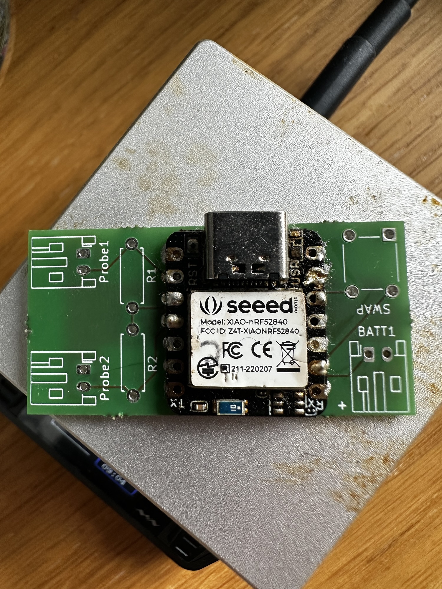
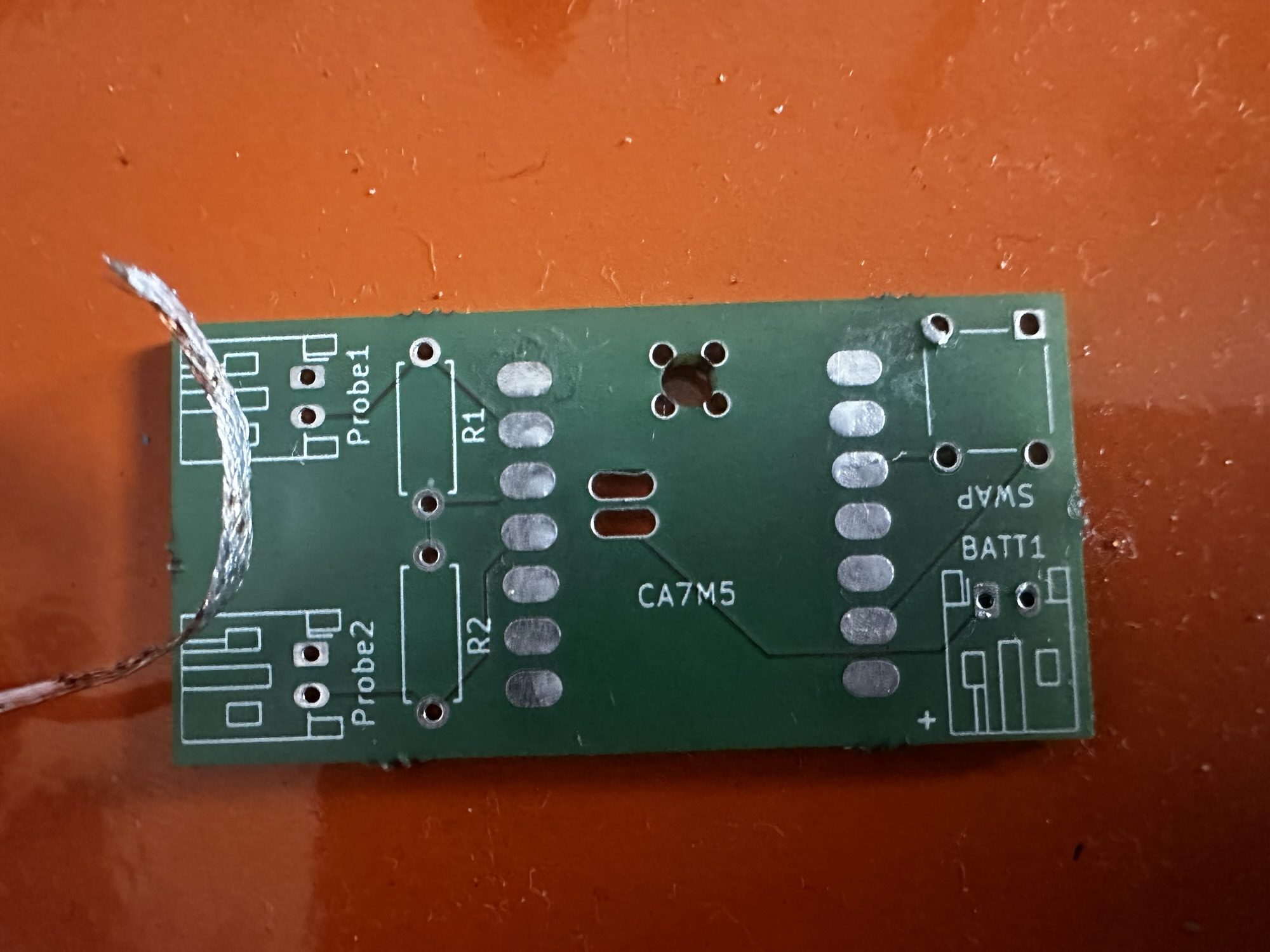
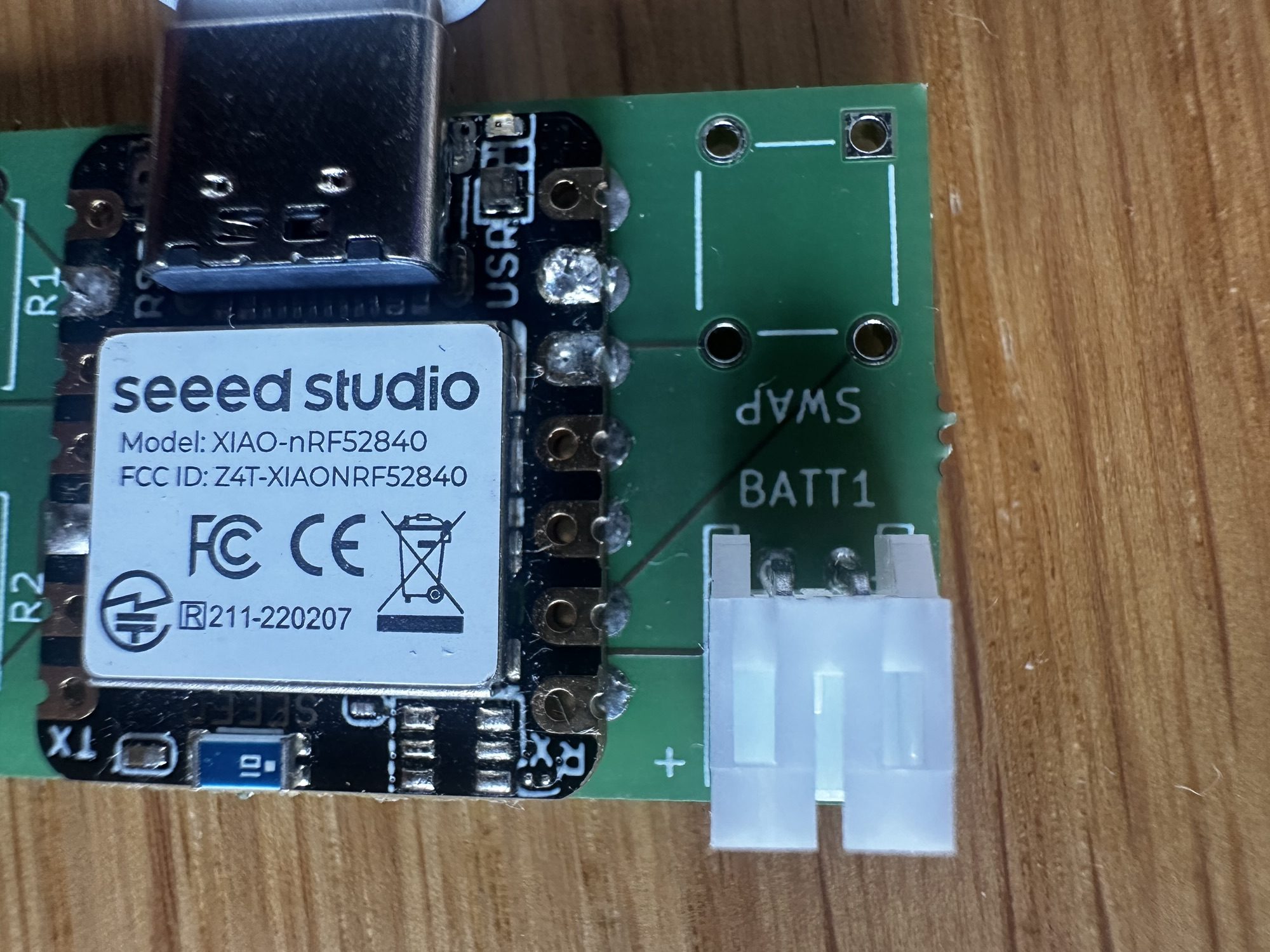
You see, the XIAO nRF52840 board I was using had the battery terminals on the bottom. I tried through hole soldering, but couldn’t make that work. I decided to try pogo pins instead.
Unfortunately, this didn’t work. The holes were too close together, so the pogo pins actually touched, shorting the battery 😦

It was at this point I decided I’d had enough. First, it took me ages to find the right header block. And then it took a few weeks for the boards to arrive.
Once I’d soldered in the pogo pins and found the design was wrong, I decided I needed a break!
Another go at the through hole approach
I had 12 PCBs sitting on my desk that used the original through hole approach. I felt they deserved another chance. I was a little wiser about soldering and had also figured out how do use my hot plate for de-soldering. This meant it was easier to remove the boards and try again.
My first problem was the through holes didn’t fully align with the battery pads. I eyeballed this in KiCad, so it wasn’t a surprise. That is a mistake to correct in a future revision.
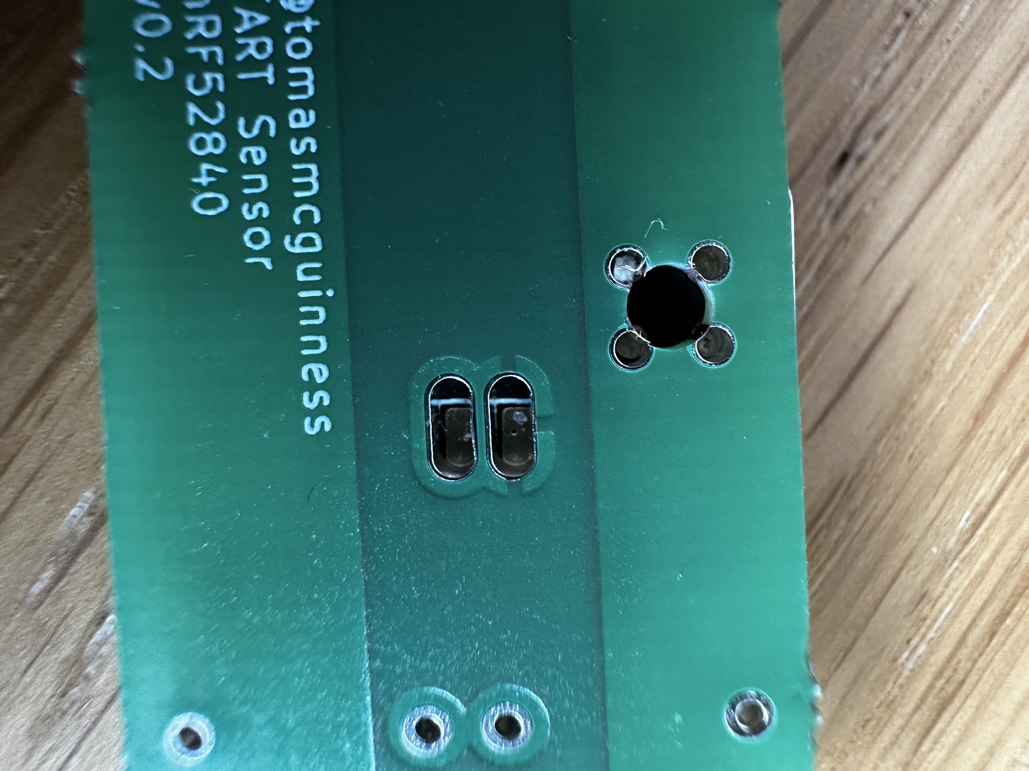
Using a clamp (from my kid’s fort-building toolbox) I clamped the XIAO onto the PCB and aligned it all.
I then applied some solder. Okay, too much solder, and I flooded the holes.

In my mind, this should have absolutely worked, yet it didn’t. These blobs appeared to have made *zero* contact with the pads on the other size. I had another go, this time being more careful with the solder.
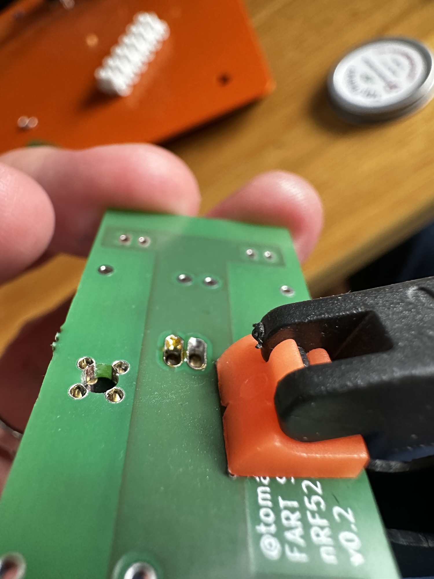
As you can see, the solder is clinging to the sides of the through holes yet not touching the pads! I proved this by removing the clamp. The XIAO lifted off.

Solder Paste
I then tried putting some solder on the battery pads. Unfortunately, as my hole are out of alignment, I couldn’t sit the XIAO flush to the PCB. My main problem was not being able to heat the battery pad. My soldering iron tip was just too fat.
I then wondered if solder paste would work better. I haven’t used it before, but it’s basically a paste that contains flux and solder. It’s typically used for surface mounting. I figured if I put some on the terminal itself and inside the through hole, perhaps they’d join once I applied a little heat.
Once my 4900P paste arrived, I gave it a try.
First, the paste wouldn’t adhere to the pads at all. It just wasn’t stick enough. A quick google revealed that the board could be warmed a little, to help the solder adhere. This phase could have gone better.

That said, I’d seen loads of videos which show solder paste melting and flowing onto the pads and copper.
The next step was choosing the reflow curve. This is a graph of temperature against time. It’s the ideal for the paste to warm up and then melt.

I programmed this in MHP50 mini hot plate. I couldn’t do it exactly, but it was close enough. The max peak temperature of 249°C caught my eye, but I carried on.
As soon as my XIAO board started smoking and bubbling, I realised I *might* have made a mistake!
My board got so hot it melted the solder on the XIAO board, totally frying it. A £10 board down the drain.
I posted this outcome on Reddit to see if I could learn anything. I got some helpful feedback.
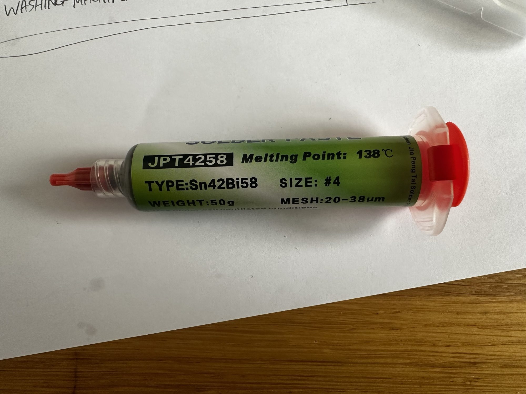
Firstly, the paste I had was actually *high temperature* paste. That didn’t help matters at all! I ordered some SN42BI48 paste, which has a lower temperature of about 140°C.
Secondly, one user showed that he had lots of success surface mounting these XIAO boards, including the rear battery pins! I had been close to giving up (again) and that gave me the drive to keep going.
Using the paste that doesn’t need the temperature of the sun to melt
With the arrival of the low temp SN42 paste, I was ready to try again.
Rather than waste another board, I cleaned up the one I used in my previous attempt using some copper roll. No point in wasting perfectly good PCBs.
It was at this point I discovered that the MPH50 couldn’t be set to match the desired reflow curve 😟.I made a note to look at firmware updates.
The times couldn’t be set short enough, nor the temeperature low enough. I just set it to 150°C. I added some small blobs of paste and popped the board onto the hot plate.
I then had some success. One of the boards worked! It powered up and was recognised by windows. Sadly, I used one of my v1 boards, which had numerous issues 🤣. Not one to look a gift horse in the mouth, I had a go on the rear pins anyway. This time I tried a little solder paste.
After a few goes, I found a technique that appeared to work. I would melt the paste in the hole and then, using a jumper wire, swish the solder around. I think this helped it flow to the copper pad on the board. All I know is, I have one surface mounted XIAO with working battery connector.
My success was short lived.
The second board I tried ended up fried in that it didn’t boot and plugging it in via USB yielded this:
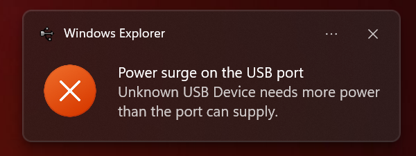
Perhaps a short across the battery terminals?
Next Steps
I have one working board, but out of two attempts, that’s not exactly great. I’ll try another two boards and see how they turn out.
Whilst it’s fun trying stuff out, I want ten working sensors before the heating season arrives. I need to stay focused!
The real problem is those rear battery terminals. I want something that isn’t fiddly and works 100% of the time. As is pointed out to me, these boards are for development. Perhaps, if there is sufficient demand for a dual temperature probe sensor, I could have one properly designed?
Thanks to Reddit, I got some suggestions for an alternative to the XIAO: The nice!nano. These have a battery terminals and integrated charger, but the pins are on the side. This is also designed to be socket mounted, which suits me!
As nice looking as the nice!nano boards are, they cost upwards of £20 each. That’s fine for a one off, but it doesn’t really scale! The Redditor also recommended a clone
https://www.aliexpress.com/item/1005007738886550.html
I have a batch of these coming from China and I’ll see how they work on the breadboard.
Stay tuned!
Did you like reading this post?
If you found this blog post useful and want to say thanks, you’re welcome to buy me a coffee. Better yet, why not subscribe to my Patreon so I can continue making tinkering and sharing.
Be sure to check out my YouTube Channel too – https://youtube.com/tomasmcguinness
Thanks, Tom!

Leave a comment