As I’m busy the porting my Zigbee Dual Temperature sensor over to Matter, I’m also moving onto the nRF54L15.
This has been mostly painless, but I’m really struggling with the ADC feature. This worked very well on the nRF52840 board, but less so on the 54l15 board. Regardless of what I do, it just seems to read 0.

The nRF ADC works by reading a voltage and then converting that to a “level” between 0 and 4096. 0 being nothing and 4096 being the max.
The most basic samples
To help figure out what’s going on, I went back to the most basic sample.
/ncs/v3.1.0/zephyr/samples/drivers/adc/adc_dtThis sample should read the value on four ADC inputs, defined in the overlay
&adc {
	#address-cells = <1>;
	#size-cells = <0>;

	channel@0 {
		reg = <0>;
		zephyr,gain = "ADC_GAIN_1";
		zephyr,reference = "ADC_REF_INTERNAL";
		zephyr,acquisition-time = <ADC_ACQ_TIME_DEFAULT>;
		zephyr,input-positive = <NRF_SAADC_AIN4>; /* P1.11 */
		zephyr,resolution = <10>;
	};

	channel@1 {
		reg = <1>;
		zephyr,gain = "ADC_GAIN_1";
		zephyr,reference = "ADC_REF_INTERNAL";
		zephyr,acquisition-time = <ADC_ACQ_TIME_DEFAULT>;
		zephyr,input-positive = <NRF_SAADC_AIN2>; /* P1.06 */
		zephyr,resolution = <12>;
		zephyr,oversampling = <8>;
	};

	channel@2 {
		reg = <2>;
		zephyr,gain = "ADC_GAIN_1";
		zephyr,reference = "ADC_REF_INTERNAL";
		zephyr,acquisition-time = <ADC_ACQ_TIME_DEFAULT>;
		zephyr,input-positive = <NRF_SAADC_VDD>;
		zephyr,resolution = <12>;
		zephyr,oversampling = <8>;
	};

	channel@7 {
		reg = <7>;
		zephyr,gain = "ADC_GAIN_1";
		zephyr,reference = "ADC_REF_INTERNAL";
		zephyr,acquisition-time = <ADC_ACQ_TIME_DEFAULT>;
		zephyr,input-positive = <NRF_SAADC_AIN6>; /* P1.13 */
		zephyr,input-negative = <NRF_SAADC_AIN7>; /* P1.14 */
		zephyr,resolution = <12>;
	};
};
Channel 0, the first, is on pin P1.11 (AIN4), based on the input-positive configuration.
zephyr,input-positive = <NRF_SAADC_AIN4>; /* P1.11 */I compiled it for the nRF54L15 and flashed my devkit.
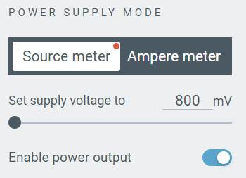
I hooked my PPKII (power profiler), set the output to 800mV and hooked it up to P1.11
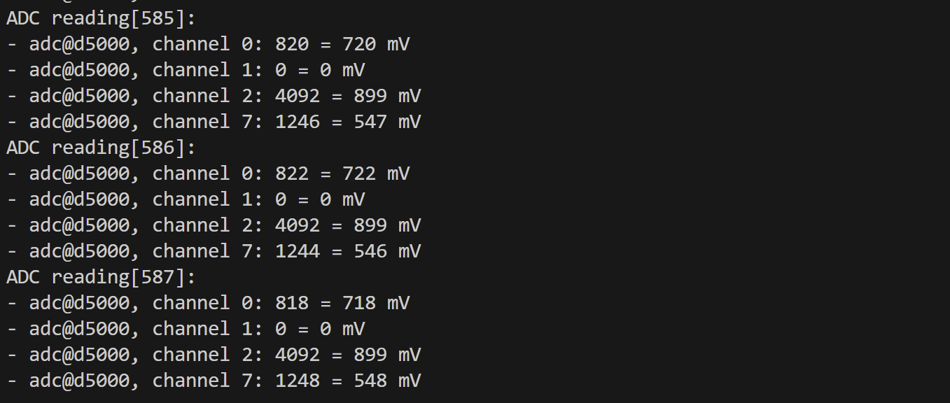
Channel 0 logged around 720mv. I checked with my multi-meter and, to my surprise, it was accurate! Well, 5mV out, but that’s not even 1%. My PPK wasn’t perhaps as accurate as I’d expected.

I took the voltage up to 1800mV in PPK II and my multi-meter caught up, showing a value of 1770mV

My nRF54L15 didn’t match this. It seems to max out at 899mV

Internal Reference Voltage
At the start, I said an ADC will report a level between 0 and 4096. But how does the ADC *know* what the max level was? This is the Reference Voltage. It defines the value that equals the top level 4096.
We tell the ADC what that value is by using the reference configuration
zephyr,reference = "ADC_REF_INTERNAL";This is where the 900mV comes from. It’s the Internal Reference voltage for the ACD.
If we have 900mV on the pin, we get 4096. If we have 450mV on the pin, we get 2048 etc. Based on this, if we apply a voltage more than 900mV, we can’t get a higher reading!
This obviously isn’t all that practical, so we can tinker a little in the form of gain.
To demonstate this, I updated the gain to adjust so it halves the input voltage.
zephyr,gain = "ADC_GAIN_1_2";As I understood it, this would enable me to read voltages up to 1800mV. Sure enough, this started to work!
I adjusted the PPK up and down from 800 to 1800mV and the ADC kept logging the corresponding mV value.
The nRF54L15 on the DK runs at a voltage of 1800mV by default. It’s a Very Bad Idea™ to apply more than the supply voltage (VDD).
Still a big confused with levels…
I’ll admit, that this only partly made sense. The really confusing part is that despite the GAIN value, the “level” registered didn’t tally with the mV value.
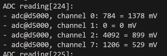
If you go back to before I adjusted the gain, the ADC logging showed this:
adc@d5000, channel 0: 1023 = 899 mVThe “level” of the ADC didn’t make sense. It was only 1024, a quarter of the maximum of 4096.
After a big of googling, I stumbled upon the answer! The number of levels is dependent on the resolution configuration! Channel 0 has a resolution of 10, which gives 1024 levels.
To confirm this, I bumped the resolution up to 12, making sure to perform a pristine build (the overlay doesn’t always get recompiled).
Sure enough, the reported level jumped to 4092! Another penny drops.

Time to apply this little bit of understanding to my Matter project.
Back to Matter
I tweaked the overlay and tinkered with some of the code, putting in similar logging. It didn’t start so well…

Turns out this error was my fault! I had removed the 2nd ADC channel from the configuration, but I was still trying to read it.
Onwards from that little mistake and my ADC started to actually work

However, the voltage was wrong. I was feeding 900mV directly to the ADC pin. Why was it reading 1800mV?
My gain value was set to ADC_GAIN_1_2 so I could read up to 1800mV.
I dropped the gain to ADC_GAIN_1 and the value changed. Now it maxed out at 899mV.

Then it hit me.
I had moved from ADC pin AIN_0 to AIN_4 (copying the sample). AIN 4 is pin P1.11, a pin I was applying power to!!! Why am I powering a pin? Well, I am planning on powering both of the voltage dividers on demand, hence the powered GPIO.
On a positive note, the temperature formula is working perfectly. A resistance of 10k in my probe equals a 25°C reading. My divider reference is 1800mV, so an output from the divider of 900mV gives an equally balanced divider.
After switching over to AIN0, this started to happen with my logging.

A reboot sorted that, but unfortunately, AIN0 was still reporting the max value.
The Pin or the Project?
I returned to the adc_dt sample and updated it to use pin AIN1.
Surprisingly, it was reporting the max value too! WTF? I reverted channel 0 to pin AIN4 to confirm.
This worked as expected. What the hell was going on?

Something must be using GPIO P1.04 (AIN0) and pulling it high. I kept doing googling and stumbled upon this: https://devzone.nordicsemi.com/f/nordic-q-a/122758/nrf54l15-uart20-on-non-standard-pins-results-in-garbage-data
In this post, the author says that P1.04 and P1.05 are being used by UART and they want to use it for ADC.
I posted my own question to Nordic https://devzone.nordicsemi.com/f/nordic-q-a/124359/ain0-and-ain1-always-returning-the-maximum-value-on-nrf54l15-dk
In an effort to keep moving, I just switched channel 0 to AIN5.
At this point, the Matter side of things just stopped working 🤣

This embedded programming is tough going.
I worked backwards, gradually aligning my project with the original template sample until it all worked again.
With one probe wired in and a 900mV voltage coming from my PPK II, iOS Home showed 25°C!
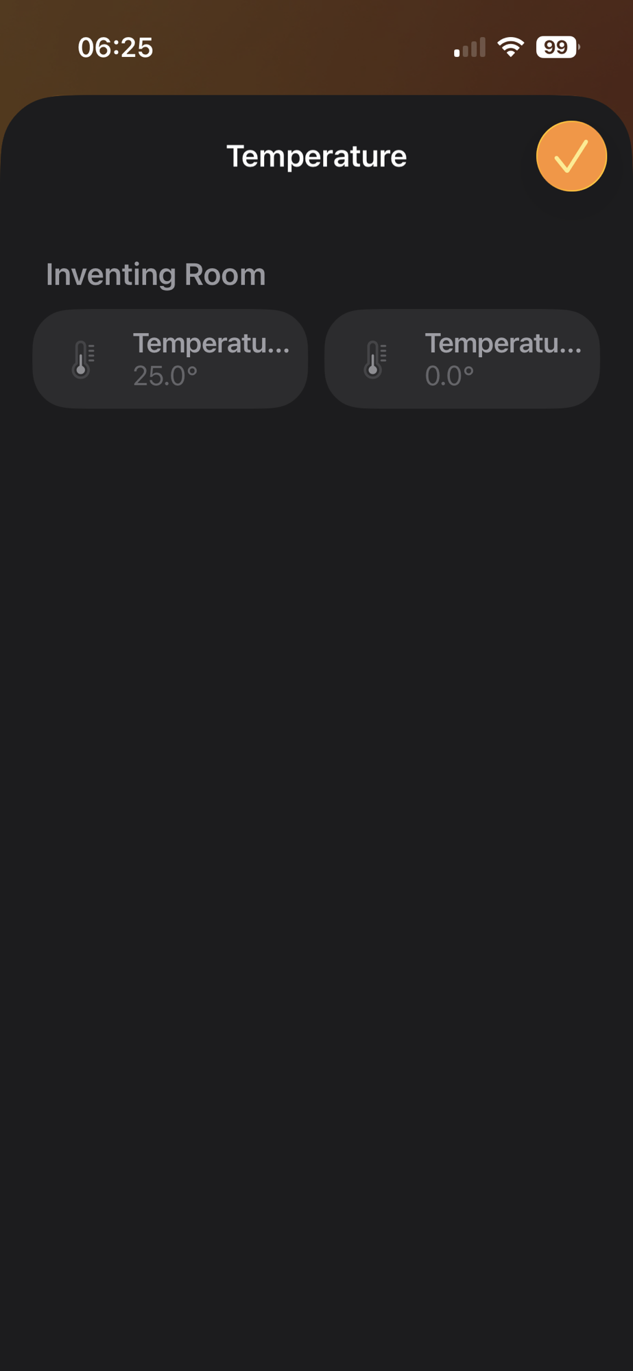
Finally!
My joy was short lived. I updated the projected to enable ADC Channel 1 on AIN6 and got a crappy reading of -5.

If I swapped the power from AIN6 (P1.13) to AIN5 (P1.12), Channel 0 would report 25 as expected.
Interestingly, if I switched off the power from the PPKII, the reading dropped to 75, so clearly *something* was working.
I was being guided in part by the nRF54L15 module I was going to use, so I had some flexibility

I tried AIN4 and AIN5.
These pins worked!
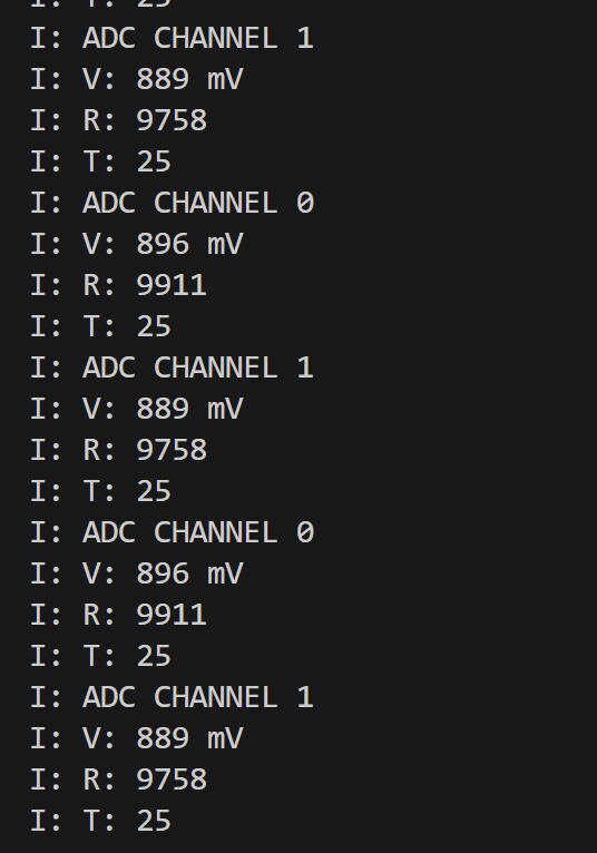
At this stage, I had two working ADC pins!
I quickly put together something with potentiometer and checked that both probes worked as expected

Summary
My initial efforts to use ADC with the nRF54L15 DK were thwarted by pins P1.04 and P1.05 being used by another peripheral. Once I realised that, I moved over to P1.11 (AIN4) and P1.12 (AIN5) without any issues.
Did you like reading this post?
If you found this blog post useful and want to say thanks, you’re welcome to buy me a coffee. Better yet, why not subscribe to my Patreon so I can continue making tinkering and sharing.
Be sure to check out my YouTube Channel too – https://youtube.com/tomasmcguinness
Thanks, Tom!

Leave a comment