
Something that’s been on my TODO list for a long time is to convert my Zigbee Temperature sensor to Matter.
I’ve written quite a few blog posts about the development of my Zigbee “FART” sensor.
If you want to read more about that, you can start here: https://tomasmcguinness.com/2024/12/09/switching-my-temperature-sensor-from-ble-to-zigbee-part-1/
The Goal
My goal was “simple”.
- Port my existing Zigbee based code over to the Matter protocol
- Find an nRF54L15 module to use instead of the XIAO board (battery pins!)
- Design a PCB for that module.

Getting Started – Porting the code
I guessed that porting the core code over to Matter should be straightforward, since Matter is basically derived from Zigbee. Clusters, attributes, endpoints and all that good stuff.
I needed to define my Matter device with two temperature endpoints, just like my Zigbee code.
I started by setting up the nRF development environment on WSL (Windows Subsystem for Linux). To use Matter with ESP-IDF I needed Linux, so I figured nRF would be the same. I started here: https://docs.nordicsemi.com/bundle/ncs-latest/page/nrf/installation/install_ncs.html
I initially tried to install using VSCode, but I kept getting horrible RUST errors. I switch to the CLI instructions instead and was up and running quite quickly. I then lost some time as I couldn’t flash anything onto my development kit, but I resolved that. Wrong version of J-Link.
Once I had the ability to build and flash some code, I mostly followed this guide: https://docs.nordicsemi.com/bundle/ncs-3.1.0/page/nrf/protocols/matter/getting_started/adding_clusters.html.
Using the ZAP tool, I added two endpoints, each with a single temperature sensor. I didn’t add the On/Off cluster.

I added a simple method to assign a random value to the Attributes
void AppTask::SensorMeasureHandler(){ TemperatureMeasurement::Attributes::MeasuredValue::Set(1, int16_t(rand() % 5000)); TemperatureMeasurement::Attributes::MeasuredValue::Set(2, int16_t(rand() % 5000));}
This gets invoked every 5 seconds by a task timer.
void SensorTimerHandler(k_timer *timer)
{
Nrf::PostTask([] { AppTask::SensorMeasureHandler(); });
}
CHIP_ERROR AppTask::Init()
{
...
k_timer_init(&sSensorTimer, &SensorTimerHandler, nullptr);
k_timer_user_data_set(&sSensorTimer, this);
k_timer_start(&sSensorTimer, K_MSEC(5000), K_MSEC(5000));
return Nrf::Matter::StartServer();
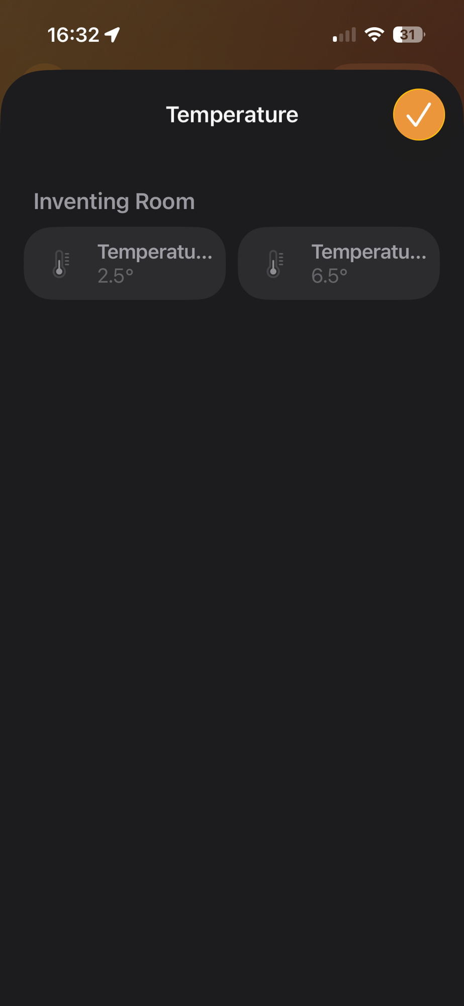
}Using iOS Home, I commissioned the device and my two sensors appeared. Nice.
Reading the actual sensor values
The flow was basically the same as my Zigbee code with one difference. I gave each probe its own power pin. Every thirty seconds, the device would turn on the power, take an ADC reading and turn off the power. It did this for both probes. The temperature gets multiplied by 100 to turn it into a Matter temperature (to allow fractions)
gpio_pin_set_dt(&probe_1_divider_power, 1);k_sleep(K_MSEC(1000));int16_t probe_1_temperature = Instance().ReadProbeTemperature(1) * 100;gpio_pin_set_dt(&probe_1_divider_power, 0);chip::app::Clusters::TemperatureMeasurement::Attributes::MeasuredValue::Set(1, probe_1_temperature);
I had lots of issues with ADC on the nRF54L15 dev kit, but got there in the end.
I used potentiometers to simulate the NTC thermistors and that seemed to work well.
Indicator Light
One thing I realised was missing, during my PCB development, was an indicator light. The light would blink slowly to tell you it’s ready to pair and rapidly when pairing. It sounds simple, but having this is really useful.
My Zigbee sensor used the LED on the XIAO board. Since I was going down the road of using a module, I needed to add my own support for it. I defined the indicator in the overlay.
leds { compatible = "gpio-leds"; led0: led_0 { gpios = <&gpio1 13 (GPIO_PULL_DOWN | GPIO_ACTIVE_HIGH)>; label = "Indicator LED"; };};
In order to trigger the indicator, I wrote my own function to handle Matter events, which I registered like this
Nrf::Matter::RegisterEventHandler(AppTask::MatterEventHandler, 0)
In this function, I used timers with different delays to blink the LED. Once a second when ready for pairing and every 200ms when being paired.
else if (isBleConnected){ LOG_INF("Bluetooth connection opened"); k_timer_start(&sIndicatorTimer, K_MSEC(200), K_MSEC(200));}else if (ConnectivityMgr().IsBLEAdvertising()){ LOG_INF("Bluetooth is advertising"); k_timer_start(&sIndicatorTimer, K_MSEC(1000), K_MSEC(1000));}
Reset Button
Just like my Zigbee code, I needed a way to reset the device. I started by adding a reset button to the overlay.
buttons { compatible = "gpio-keys"; button0: button_0 { gpios = <&gpio1 14 (GPIO_PULL_DOWN | GPIO_ACTIVE_HIGH)>; label = "Reset Button"; };};
Then I wired up a callback using an interrupt
if (!gpio_is_ready_dt(&reset_button)){ LOG_ERR("Cannot configure reset button"); return;}gpio_pin_configure_dt(&reset_button, GPIO_INPUT);gpio_pin_interrupt_configure_dt(&reset_button, GPIO_INT_EDGE_BOTH);gpio_init_callback(&reset_button_cb_data, AppTask::ResetButtonCB, BIT(reset_button.pin));gpio_add_callback(reset_button.port, &reset_button_cb_data);
The ResetButtonCB function would start a timer when the button was pressed. If the button is released, the timer was cancelled. If the timer fires, the reset method is called.
chip::Server::GetInstance().ScheduleFactoryReset();
Choosing an nRF Module
When I started looking for an nRF54L15 module, the first one I found was the HolyIoT module.
I got two and one of their development kits. I didn’t have a great experience with power consumption on their board. I also found they didn’t really have KiCad (PCB) support.
The second board I looked at was the MinewSemi ME54BS01. MinewSemi also offered a DK board.
What set them apart from the KiCad support
PCB
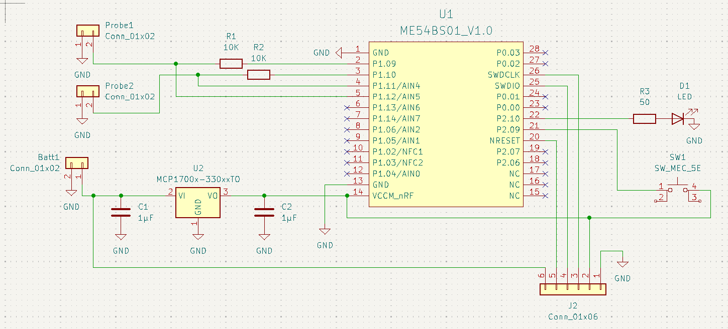
Using KiCad, I put together a PCB design around the ME54BS01. The main differences between this and my Zigbee design are:
- Use of a module instead of a full XIAO dev board.
- LDO to regulate the battery voltage.
- SWD pins for flashing and debugging.
- Indicator LED
Thanks for people of Reddit who pointed out issues with my design!

As I finish this post, I’ve ordered three boards from Aisler. Fingers crossed this design will be fine!!!
Next Steps
At this point, I’m just waiting on Aisler to fabricate and deliver my boards!
Once I take delivery, I’ll try and solder on the various components. This PCB is a mix of surface mount and through hole, so I’ll be trying stuff I’ve never done before.
Should make for an interesting post and YouTube video!
Did you like reading this post?
If you found this blog post useful and want to say thanks, you’re welcome to buy me a coffee. Better yet, why not subscribe to my Patreon so I can continue making tinkering and sharing.
Be sure to check out my YouTube Channel too – https://youtube.com/tomasmcguinness
Thanks, Tom!

Leave a comment