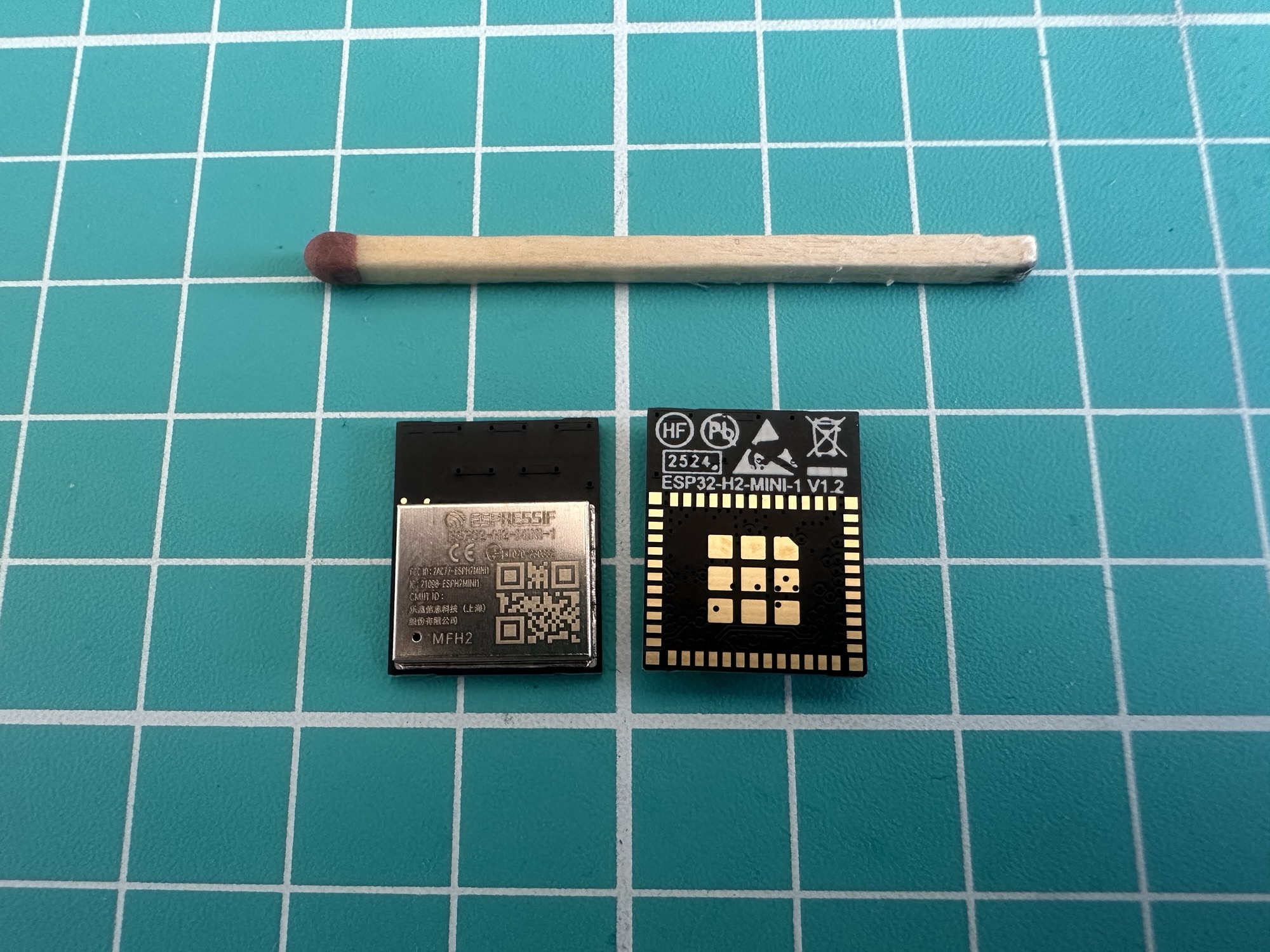
This is the first ESP32 PCB I’ve designed. Hot on the heels of my nRF54L15 devkit, I decided to give the ESP32-H2-MINI-1 a go.
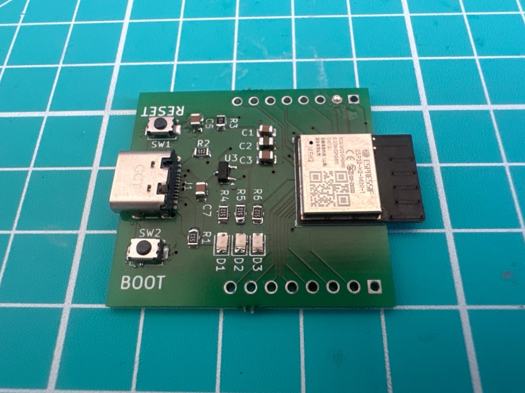
I wanted to push myself, by designing something a little more complicated. This board featured the small ESP32-H2-MINI-1 module, two buttons, three LEDs and a USB-C connector! I also exposed most of the GPIOs via header pins.
There was no real goal for this board, rather it was just an exercise in learning. I wanted to assemble it, connect it to USB, flash a Blink sample and bask in the glory of a flashing LED.
TLDR; It didn’t really work as intended as I made one fundamental mistake. It wasn’t a complete failure though as I got an LED to blink.
Assembly
The main challenges for assembly were the USB-C connector and the ESP32-H2-MINI-1. The USB-C connector, whilst it had tiny pins, had accessible pins, meaning I could use my soldering iron if needed. The ESP32-H2-MINI-1 was a different beast. All its pads are a) tiny and b) underneath.
Without a stencil to guide me, I applied some low temperature solder paste, placed the components in position and popped it on the hot plate.
Everything seemed to move into place, but I had put down too much paste under the ESP32-H2. I even saw some leaking out!
I plugged in the USB cable. At this point, I expected both D1 (5V present) and D2 (3.3V present) to light up. These LEDs had nothing to do with the H2, they were just power indicators. Sadly, nothing happened.
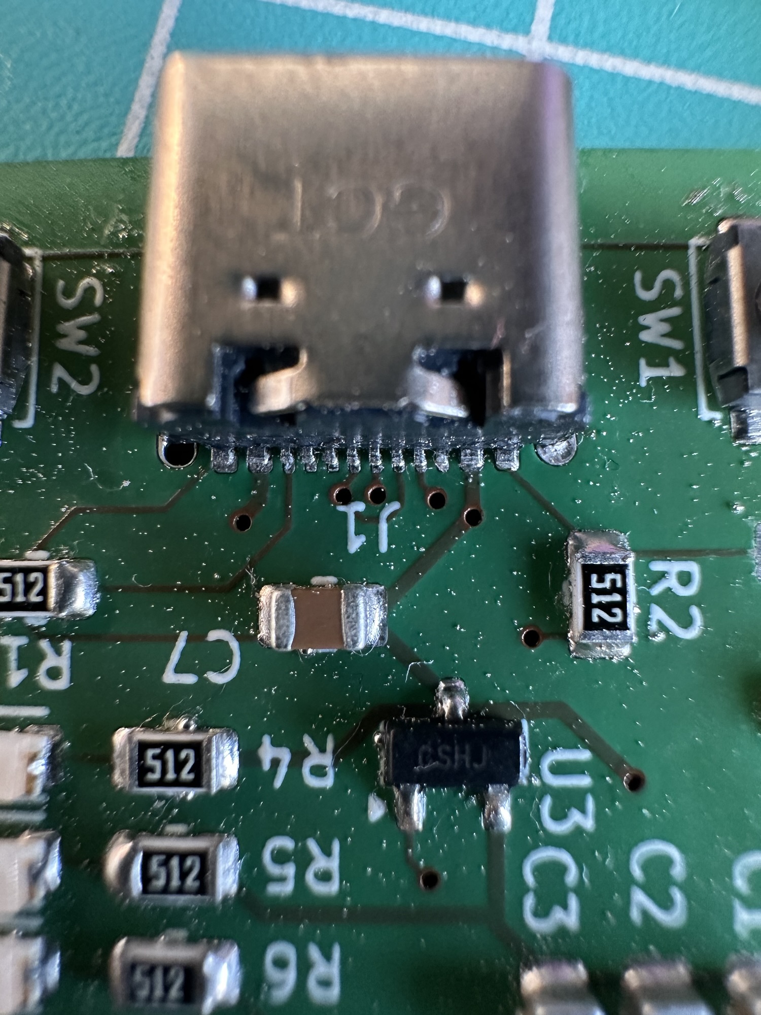
Undeterred, I checked some of the voltages and the board was dead. This meant the USB wasn’t supplying any power. I removed the USB-C connector, cleaned the pads and tried again; this time I tinned the tiny pads before seating the component. Once it was soldered in place, I ran my iron over the pads, ensuring there were no bridges.
This time I got some LEDs when I connected it up!
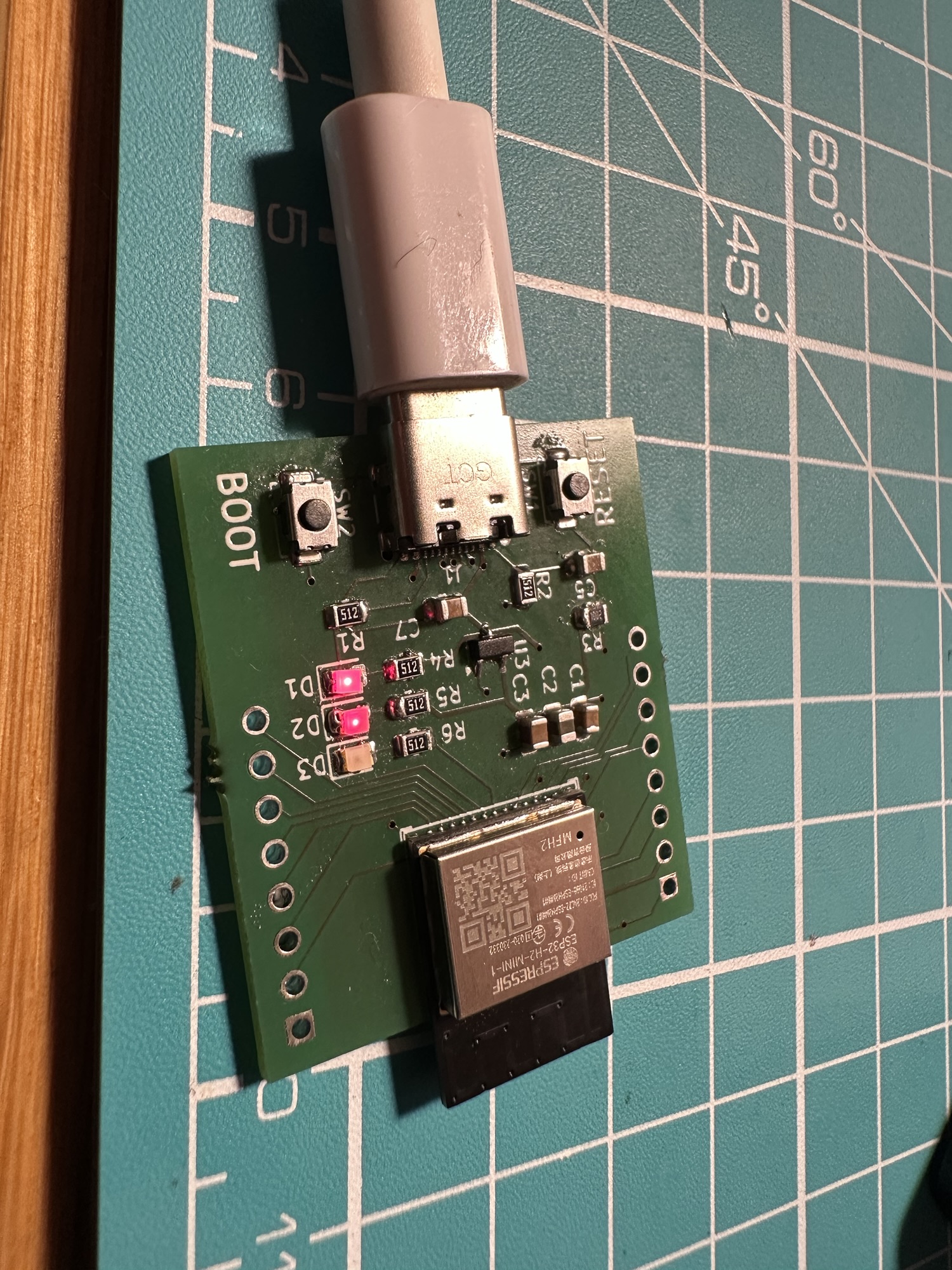
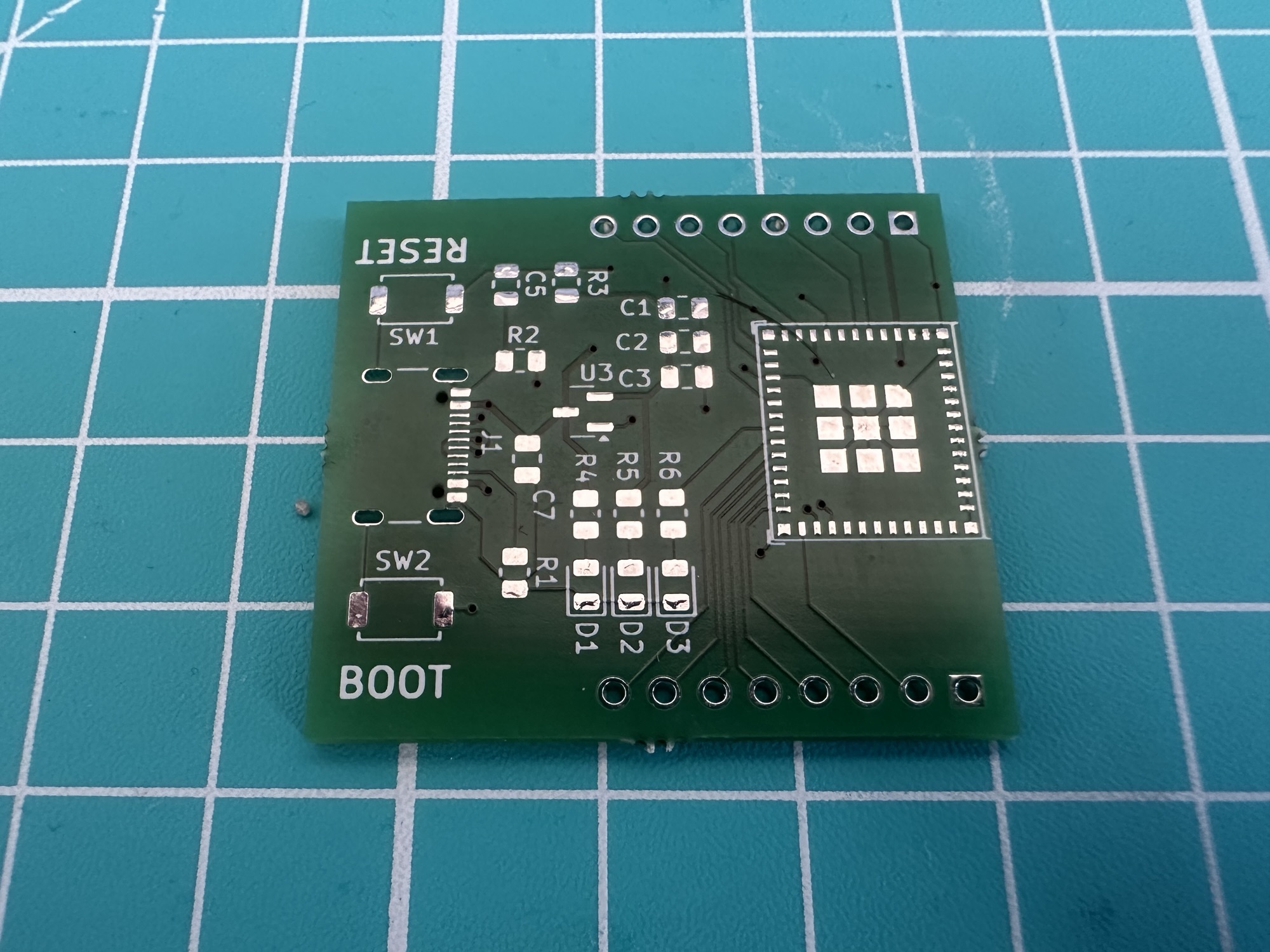
Whilst the board was now being powered, the USB connection didn’t appear on my PC. Looking at the image, you can see that the ESP32 wasn’t really seated correctly. All the pads are underneath the module, so nothing should be visible!
I made another attempt. I cleaned up the pads and the module and tinned everything before heating it up. Whilst it looked much better, it still didn’t work.
With the help of Claude, I determined there was a bridge somewhere. On the board, there is an EN pin. This pin needs 3.3V to ENable the board. Nothing will happen if this isn’t pulled high. With my multi-meter, I found that the R3/C5 RESET button was only showing 500mV on the other side of R3. This meant that no matter what, the board would not start.
After experimenting, by removing both the capacitor and resistor, I figured I probably had a short under the board. So, I took it off, cleaned it and put it back on, even more carefully this time.
A COM port! It’s gone. It’s back. It’s gone.
On reconnection, my windows PC started emitting the “device connected” and “device disconnected” chimes over and over again. The Windows device manager even showed COM3, but it constantly refreshed itself.
This pattern made me think the H2 was restarting. Perhaps it was pulling too much power?? The MCP1700 LDO I had chosen could delivery 250mA. According to the datasheet, the H2 wouldn’t use more than 140mA. To confirm this, I connected my Nordic Power Profiler to an Espressif DevKit. The trace showed a spike of 200mA on startup.
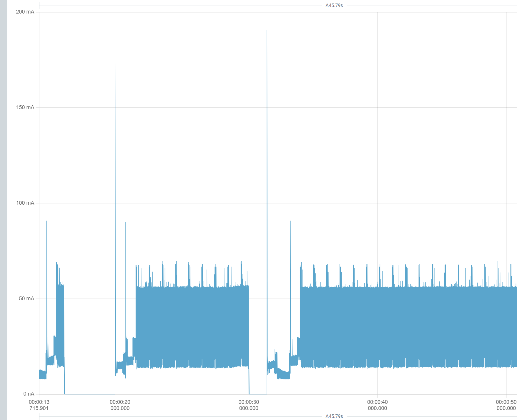
More than the datasheet, but well within the capabilities of the MCP. I ruled out resets due to power.
Out of curiosity, I tried the esptool command line tool. I wanted to see if I could query the chip over the USB connection. Amazingly, it worked and it detected the chip and read it’s MAC address!
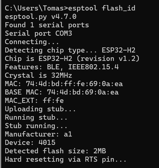
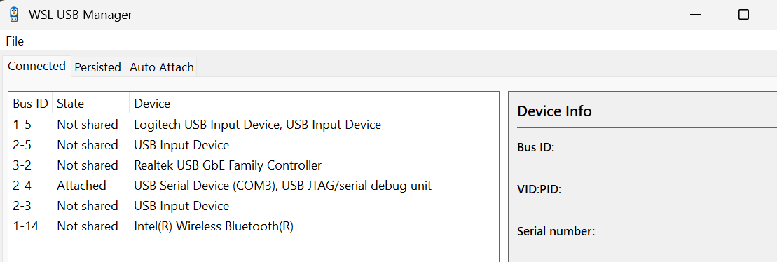
The USB connection also stabilised, with the constant chimes stopping. There were clearly some mistakes with my PCB, but there was a connection, which was brilliant! It even showed as USB JTAG in the WSL USB Manager app (which I use with my Windows Subsystem for Linux)
This meant I could try and run some code!
Flashing the board…
For the first bit of code, I used the trusty Blink sample! Doesn’t everyone? This is available in the esp-idf samples
esp-idf/examples/get-started/blink
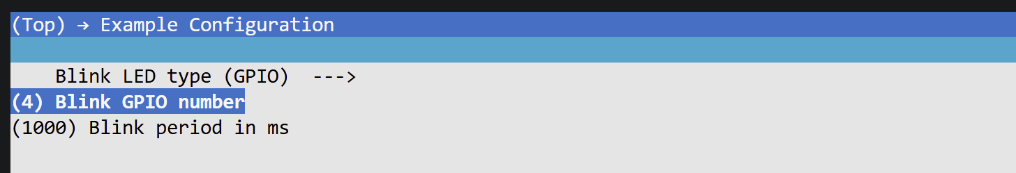
I configured it to use GPIO and set the GPIO to 4 as that’s connected to D3 on my board.
I compiled and flashed and ….
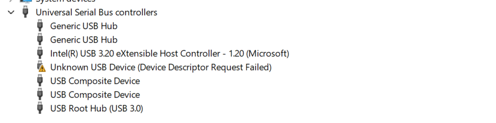
With some code flashed onto the chip, the USB behaviour changed. When I reconnected it, the COM port didn’t appear at all. The LED did start to blink, but no COM Port. I repeated this a few times and sometimes a COM port would appear, but mostly it would show an unknown device
What did I do wrong?
The primary mistake related to strapping pins GPIO8 and GPIO9. They are needed at boot time to control *how* the chip boots.
I only went and connected the BOOT button to the wrong PIN. If that wasn’t bad enough, I also didn’t connect GPIO8 at all (leaving it floating, which is bad)
In the case of the BOOT button, I made a classic PIN vs. GPIO mixup! I connected my boot button to PIN 9, rather than GPIO9! According to the sample peripheral schematic, GPIO9 (pin 23) should be connected to the boot button.
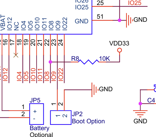
You can also see in the diagram that GPIO8 (pin 22) should be pulled high. I probably ignored this pull-up since I didn’t know what it did.
Aside from this large mistake, I also made a smaller mistake. In the same diagram, it shows I’m also using too many decoupling capacitors. I’m using three, when two is enough (C1 and C2).
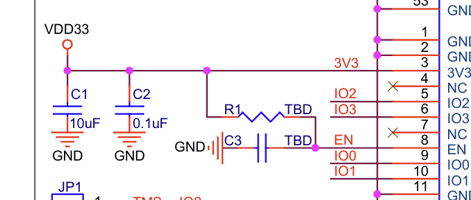
This isn’t an issue, but it makes the board more complicated than it needs to be.
Summary
Whilst my board didn’t behave as desired, the PCB wasn’t a complete failure! I have to remind myself that I’m a newbie and mistakes are going to happen. The main thing is that I learned something. As I’ve got GPIO8 and GPIO9 exposed via the headers, I’m going to try and hack the board with some 10KΩ resistors. If nothing else, this should give me some usable boards that I can practice with.
When time permits, I’ll tweak my existing PCB design and get Aisler to fabricate a few more. They will take a few weeks to arrive, but I’ll do another post when they do. Hopefully with a 100% success rate!
Did you enjoy this post?
If you found this blog post useful and want to say thanks, you’re welcome to buy me a coffee. Better yet, why not subscribe to my Patreon so I can continue making tinkering and sharing.
Be sure to check out my YouTube Channel too – https://youtube.com/tomasmcguinness
Thanks,
Tom!

Leave a comment