
After last winter’s pseudo successful radiator monitoring, I picked this project again at the end of July and decided I’d have another go. This winter would be especially different as my house would be powered by an ASHP (My Heat Pump Installation – Part 1)
I wanted to make sure my Heating Monitor was also up and running.
PCB Updates
The most recent version of the PCB, running a MinewSemi module had two flaws:
- The reset/wake button didn’t work. This was because it was connected to a GPIO port that wasn’t accessible when the CPU was asleep. As the device was mostly battery powered, this was almost all of the time.
- The other issue was the battery power. I had opted for a battery connector and LiPO batteries, meaning the deployment was very bulky.
Aside from these issues, the board & firmware worked perfectly. Low power consumption and reasonably tidy footprint (apart from the battery hanging off!)
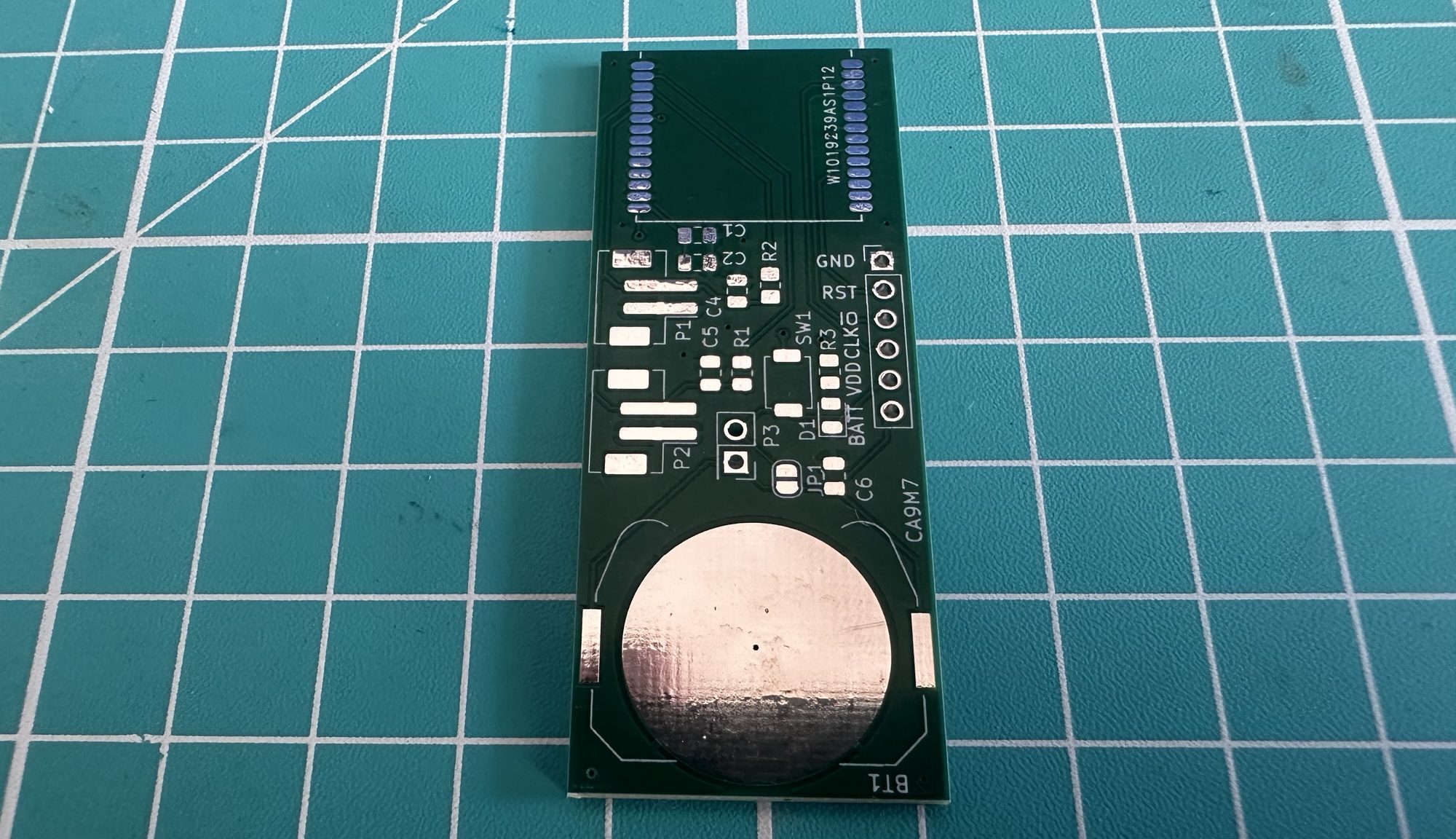
The first issue I needed to fix was the reset button. I moved from GPIO PORT 2 over to GPIO PORT 1.
I also introduced some capacitors across the voltage dividers to ensure a more stable reading.
In addition to those fixes, I wanted to try something different. The previous version used an 1.8V LDO, allowing it to be connected to LiPO batteries (4.7V). The LDO had a very low consumption, so it wasn’t really an issue, but as I played with KiCad, I wondered why I couldn’t just use a coin battery directly. The nRF54L15 worked from 1.8V up to 3.6V.
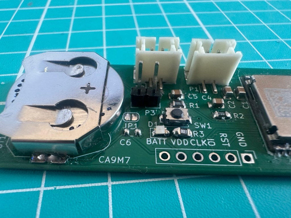
Finally, I changed the orientation of the temperature probe connectors from horizontal to vertical. The goal here was to “hide” the sensor inside the radiator. I hoped that having the probes come in from the top would make that easier.
Running directly on a battery
Unlike the espressif ESP range which has a fixed voltage of 3.3V, the nRF54 range works across a wider range of 1.8V to 3.6V. This makes it suitable to run directly with a battery like the 2032 coin cell.
My primary concern was how I’d do the voltage divide calculations without a fixed reference voltage. After a lot of reading, it turns out I was being silly. The reference voltage itself wasn’t important as I only needed a ratio from the ADC. The ADC reading could be used directly to give me the resistance of the NTC probe, which was all that mattered!
Spurred on by this revelation, I also looked at how I could use the ADC to take a battery measurement. To my delight, I could use VDD as an input to the ADC. This meant I didn’t need my own voltage divider or trace to the battery.
Using the breakout board I created (Assembling and flashing my custom nRF54L15 board), I experimented with both ADC and Battery readings. Both worked as the documentation said they would!
This meant I could eliminate two decoupling capacitors and the LDO from my design.
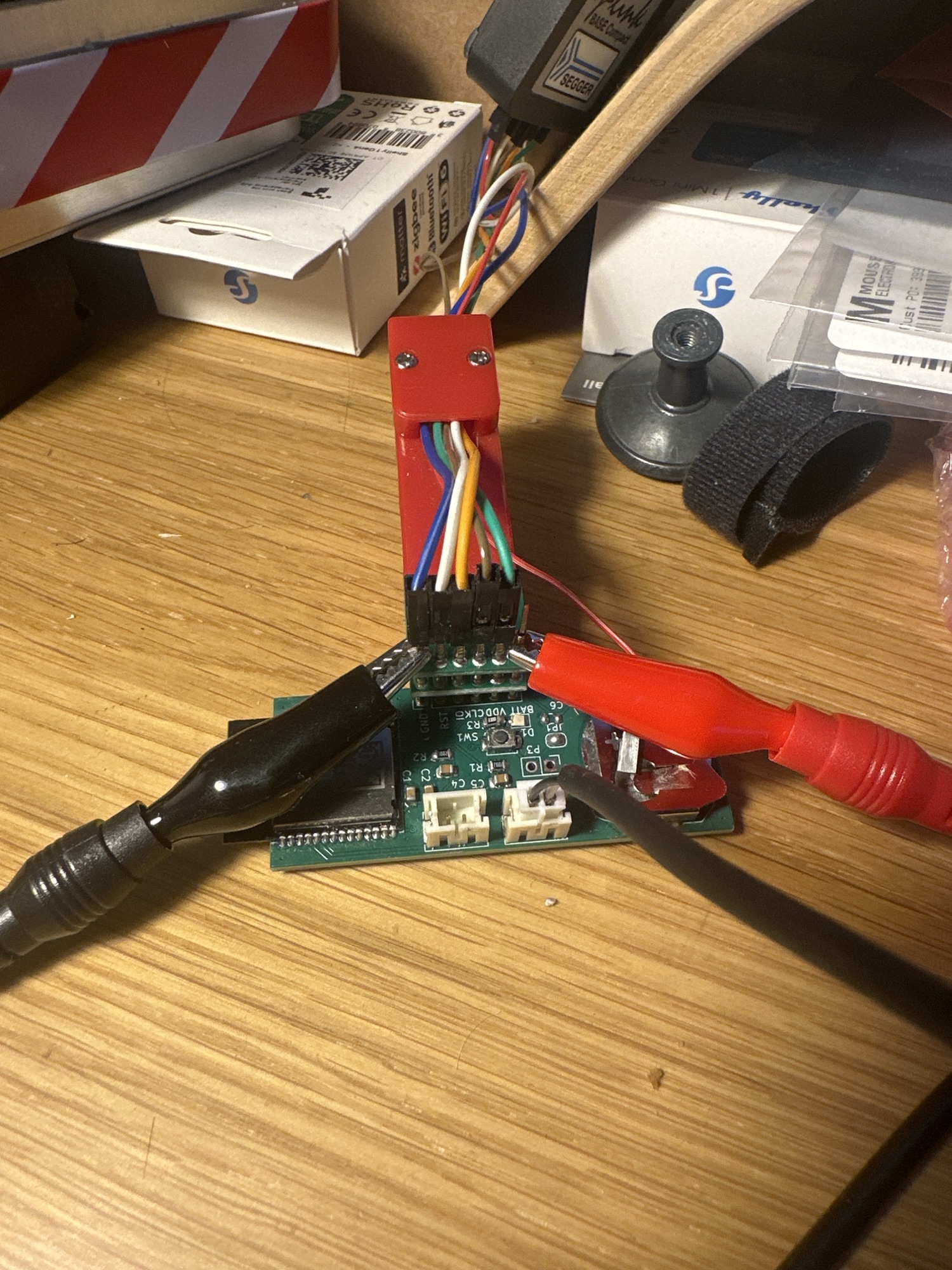
The downside to removing the LDO is that I can no longer power my board using the VDD from my J-Link interface! This meant I had to dig out my bench supply and use that to supply the necessary 3V using some crocodile clips!
Battery Voltage
Take a battery reading via the ADC was really straight forward. An ADC channel is setup as usual, but the input is set to be NRF_SAADC_VDD. Simple as that.
channel@2 { reg = <2>; zephyr,gain = "ADC_GAIN_1_4"; zephyr,reference = "ADC_REF_INTERNAL"; zephyr,acquisition-time = <ADC_ACQ_TIME_DEFAULT>; zephyr,input-positive = <NRF_SAADC_VDD>; zephyr,resolution = <12>; zephyr,oversampling = <8>;};
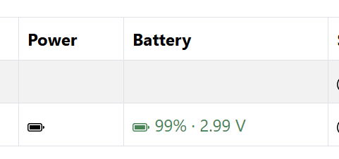
I then added the Battery Percentage and Battery Voltage attributes to the Power Source cluster in Matter and that was it!
ADC Changes & Challenges
Whilst getting the battery level was easy, moving VDD directly to the battery presented a big challenge when it came to my temperature readings.
The sensor was designed to connect to NTC Thermistors (Negative Temperature Coefficient) to take readings. These work by changing their resistance relative to temperature. To work out their resistance, a voltage divider is used. In my previous design, I could make a safe assumption about the reference voltage of the divider as it came from a fixed LDO.
Now that VDD was the battery, the voltage could be anything from 3V down to 2V, depending on the power in the battery!
That meant changing my code, so it now reads the battery level before triggering the voltage divider logic. As the voltage changes, the code should adjust.
Battery Life
To help measure the power consumption, I added some dedicated current measurement headers to my board.
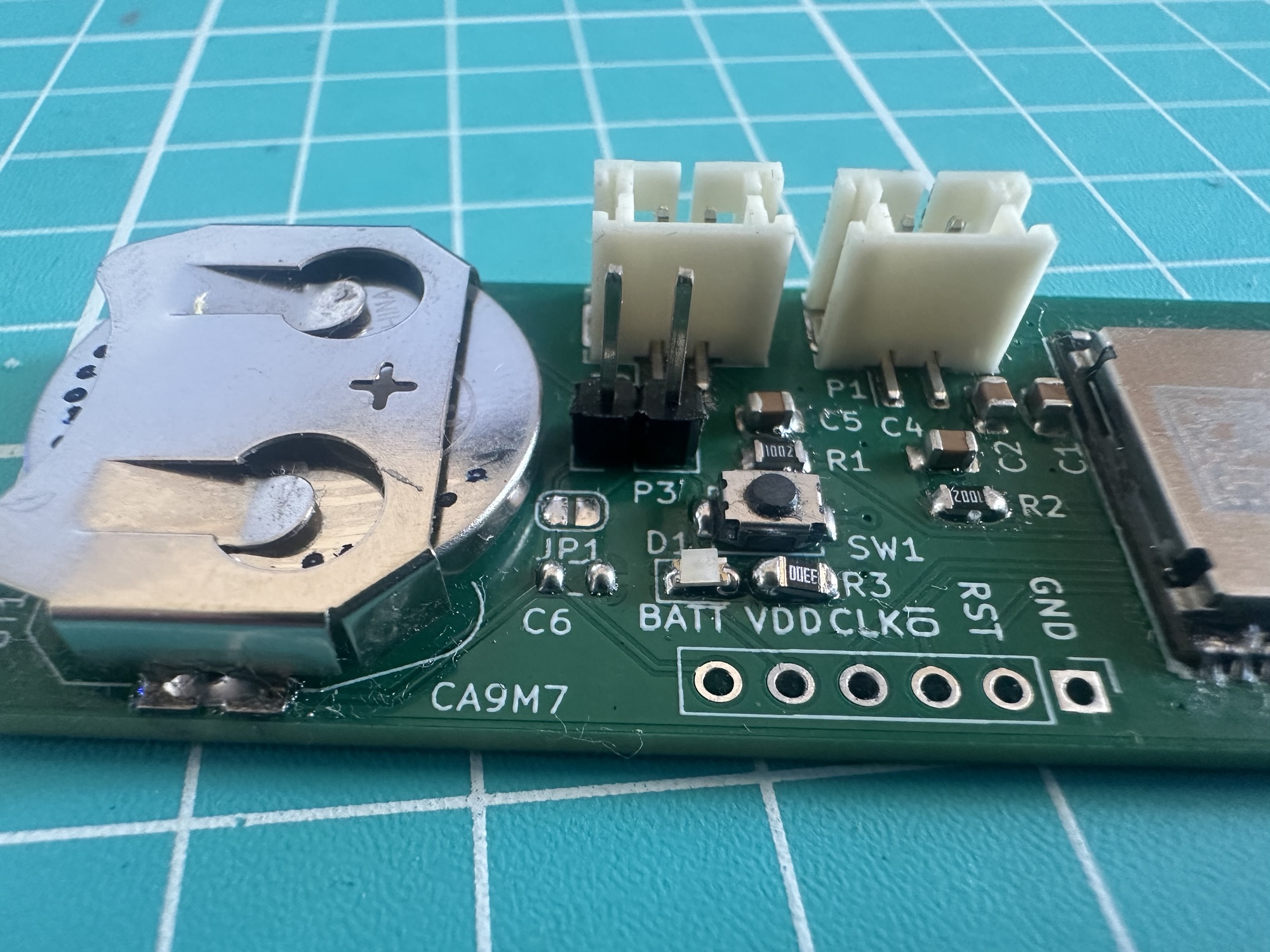
In combination with the JP1 solder bridge, visible just below the P3 header, the board can run directly (solder bridge closer) or via the header.
To measure the power, I used the Nordic Power Profiler Kit II (one of the best bits of kit I ever got!). On powering it up, on a coin cell, the consumption is high as the board is advertising via Bluetooth and turning its LED on and off.
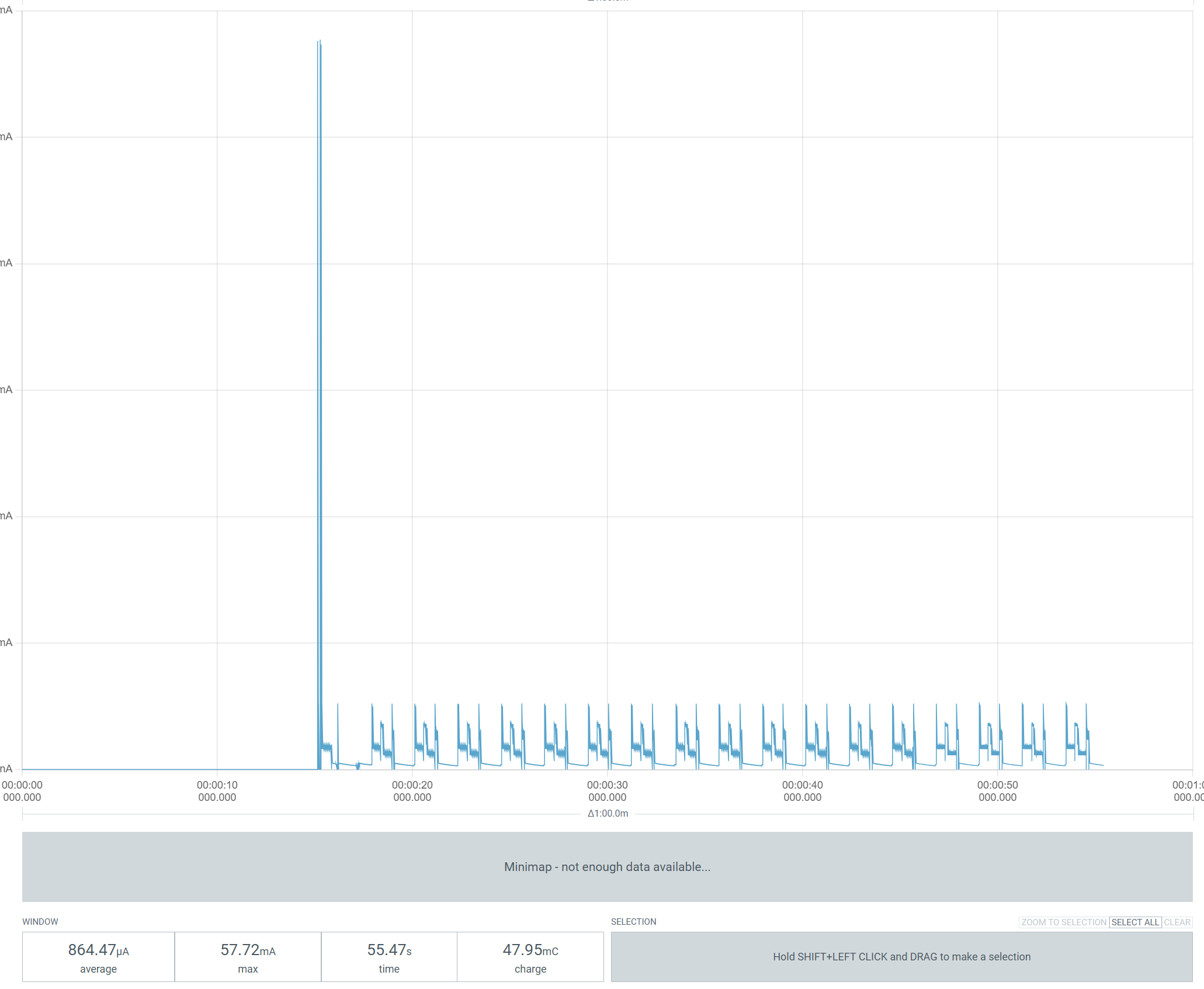
Once the board has been commissioned and the ICD (Intermittent Connected Device) is setup, the consumption plummets.
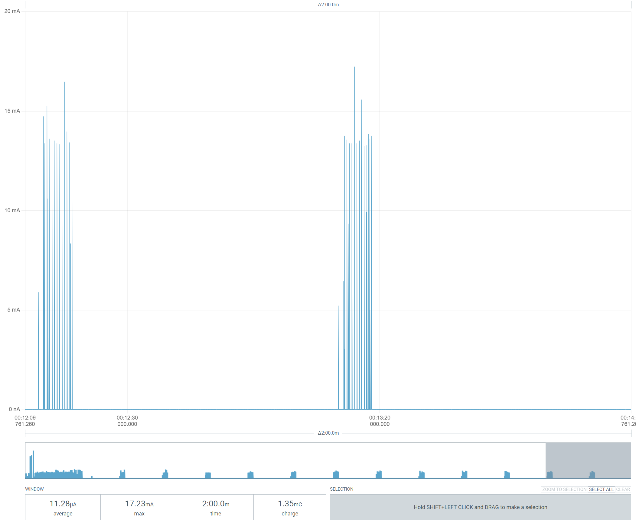
With a reading every minute, the consumption falls to 11uA over two minutes.
At 11uA, a typical coin cell could last for more than 2 years, but the battery will degrade over time, so I think a year is a reasonable expectation. Not bad!
Next Steps
With the board working as expected, I need to make up nine more of them and add them into my heating monitor.
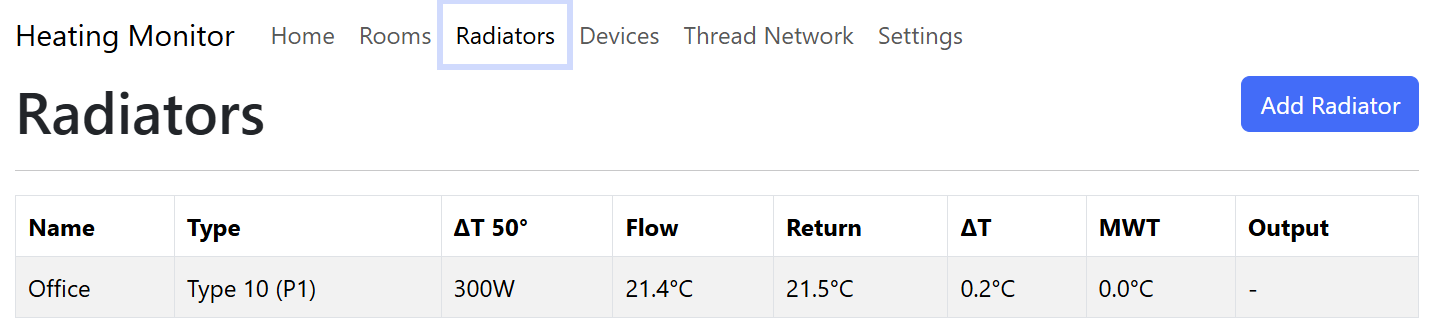
Once the weather gets a little colder, I will check the temperature accuracy. I can’t imagine it will be off by very much.
Everything is open source and up on GitHub
https://github.com/tomasmcguinness/matter-nrf-dual-temperature-sensor
Did you enjoy this post?
If you found this blog post useful and want to say thanks, you’re welcome to buy me a coffee.
Be sure to check out my YouTube Channel too – https://youtube.com/tomasmcguinness
Thanks,
Tom!

Leave a Reply