
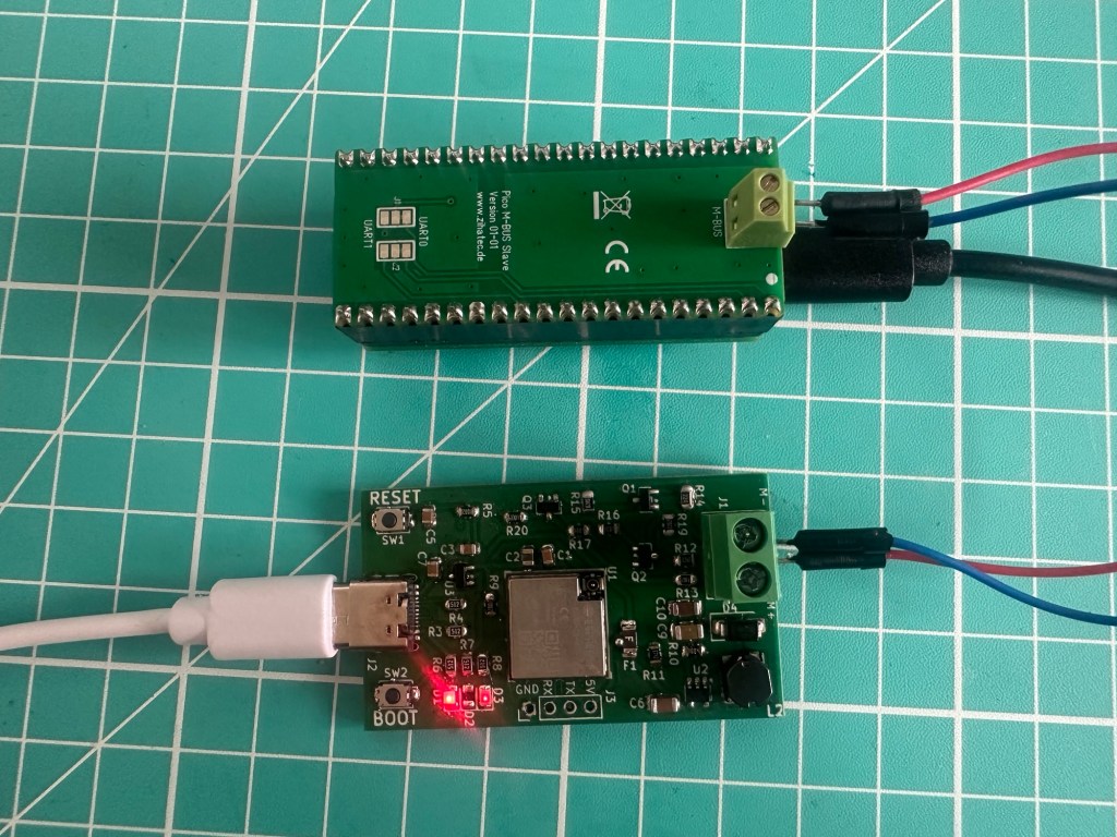
With my Revision F boards all soldered up and debugged, I was ready to make my first MBus communication attempt!
In this post, I’ll run through the process.
Issues with Revision F
Before diving into the test, I thought it might be helpful if I gave a quick through some of the mistakes I made soldering up my Revision F board.
Booster diode the wrong way around
I did a whole post on this issue! Seems I mistook a vague white line for the polarity indicator.
Swapped Capacitor and Resistor
This took a while to find! I couldn’t get the USB connection to work. I reflowed both the USB connector and ESP32, which helped, but eventually I found the problem! C7 and R4 had their components swapped! Have a look at the image below and you should be able to spot the issue!
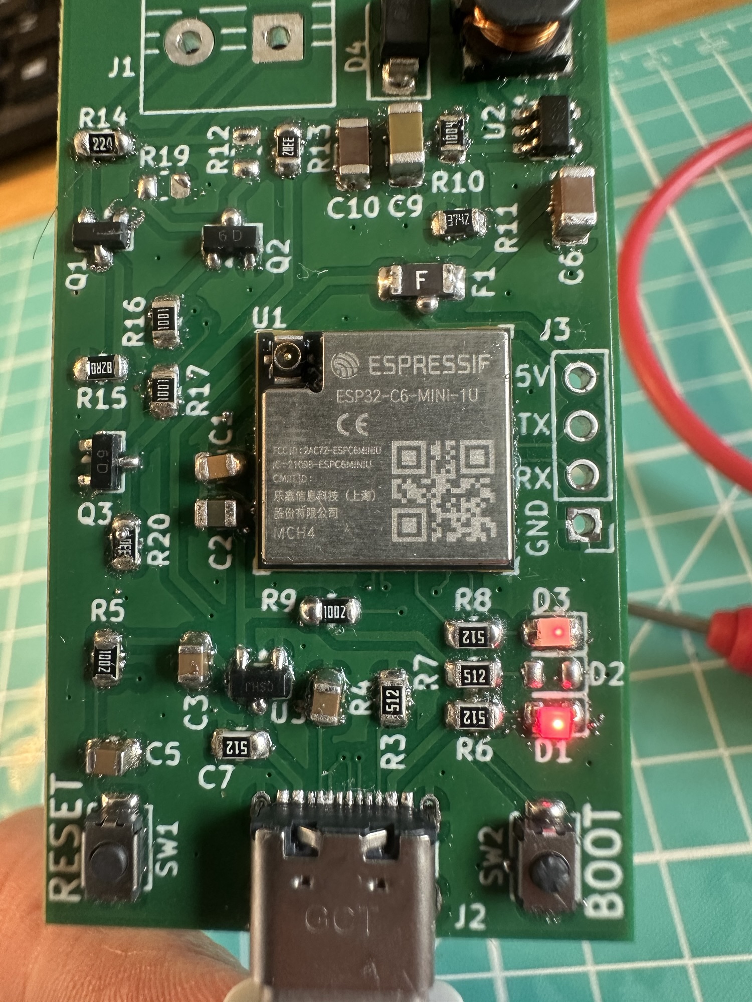
Swapping them back allowed the USB connection to work!
Q1 MOSFET was an NPN, not a PNP.
Essentially, the Q1 MOSFET was the wrong type. With Claude’s help, we worked through the various test points and realised that Q1 wasn’t doing the right thing.
The result was incorrect voltages on the M- and M+ terminals. After swapping Q1, the voltages normalised to 34V and 22V. Close enough to the 36V and 24V required levels required for the MBus protocol.
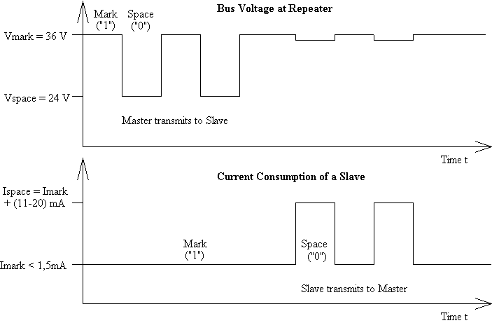
This Master wouldn’t manage many slaves (have we not discarded this terminology??), but for one-to-one comms it should be enough.
I haven’t a clue how I put the wrong component in, but it looks like I did.
I also made a mess of the initial replacement too. I tried to replace it with a soldering iron, but I made a hash of it.
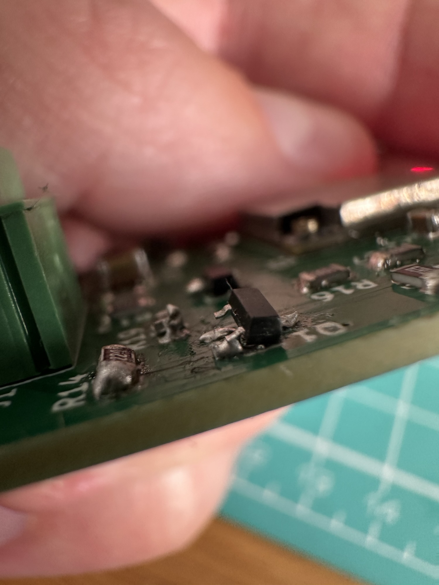
In the end I used my hot plate and copious amounts of flux to reseat it. Once it was done, the MBus terminals started to behave as desired, switching between 34V and 22V based on the UART1 TX.
Testing the Master can speak MBus
With the board appearing to work, the next step was to hook it up to an MBus slave and see if they could talk to each other. Rather than connect it to an *actual* MBus device and risk breaking it, I decided it would be better to use a device I had more control over. To that end, I purchased an RPi Pico with an MBus Slave Hat.
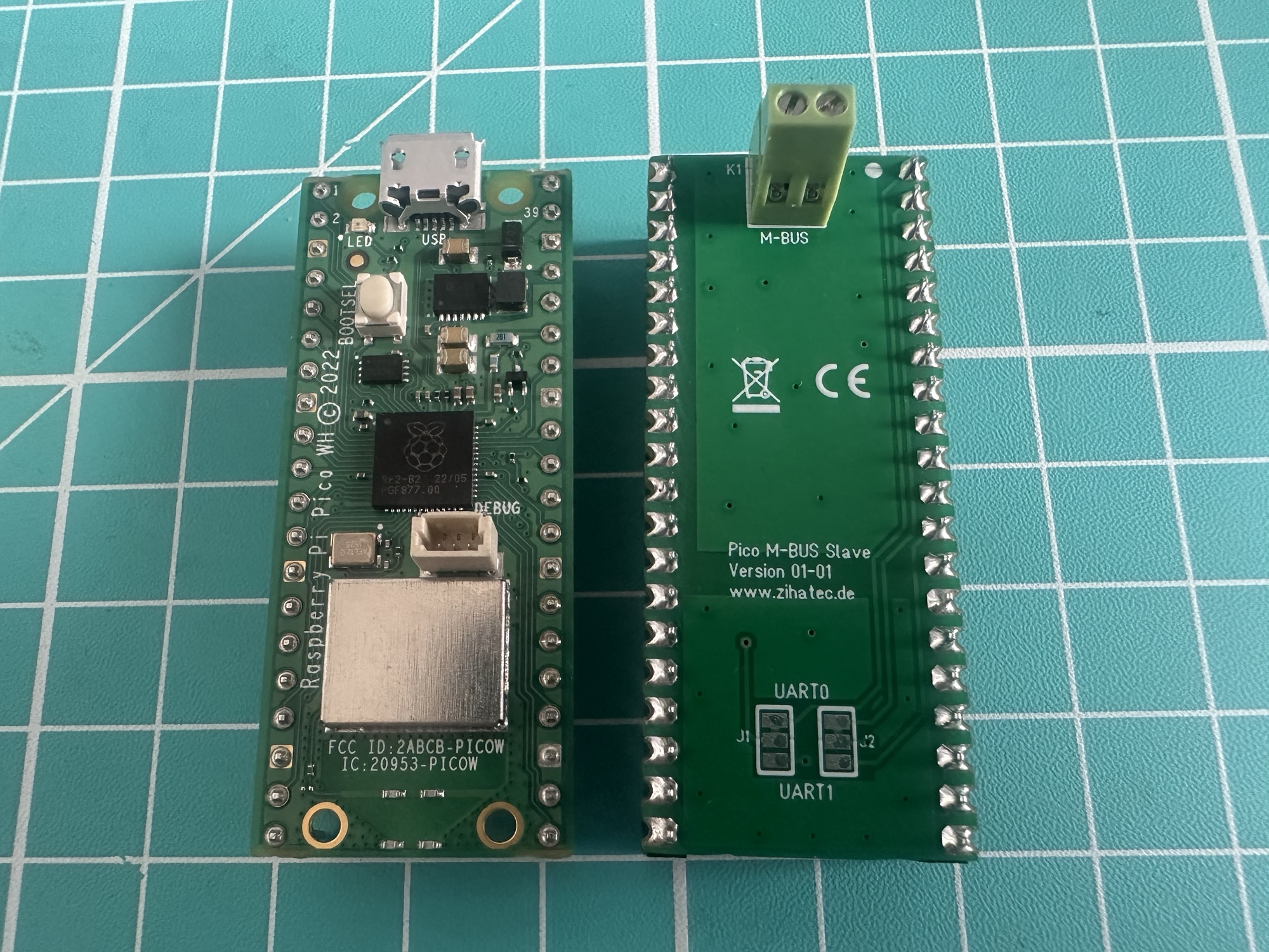
I grabbed this Arduino-MBUS-Meter example Arduino sketch and flashed it onto the PICO (using macOS as I could get it to work in Windows). I then wired the two devices together…
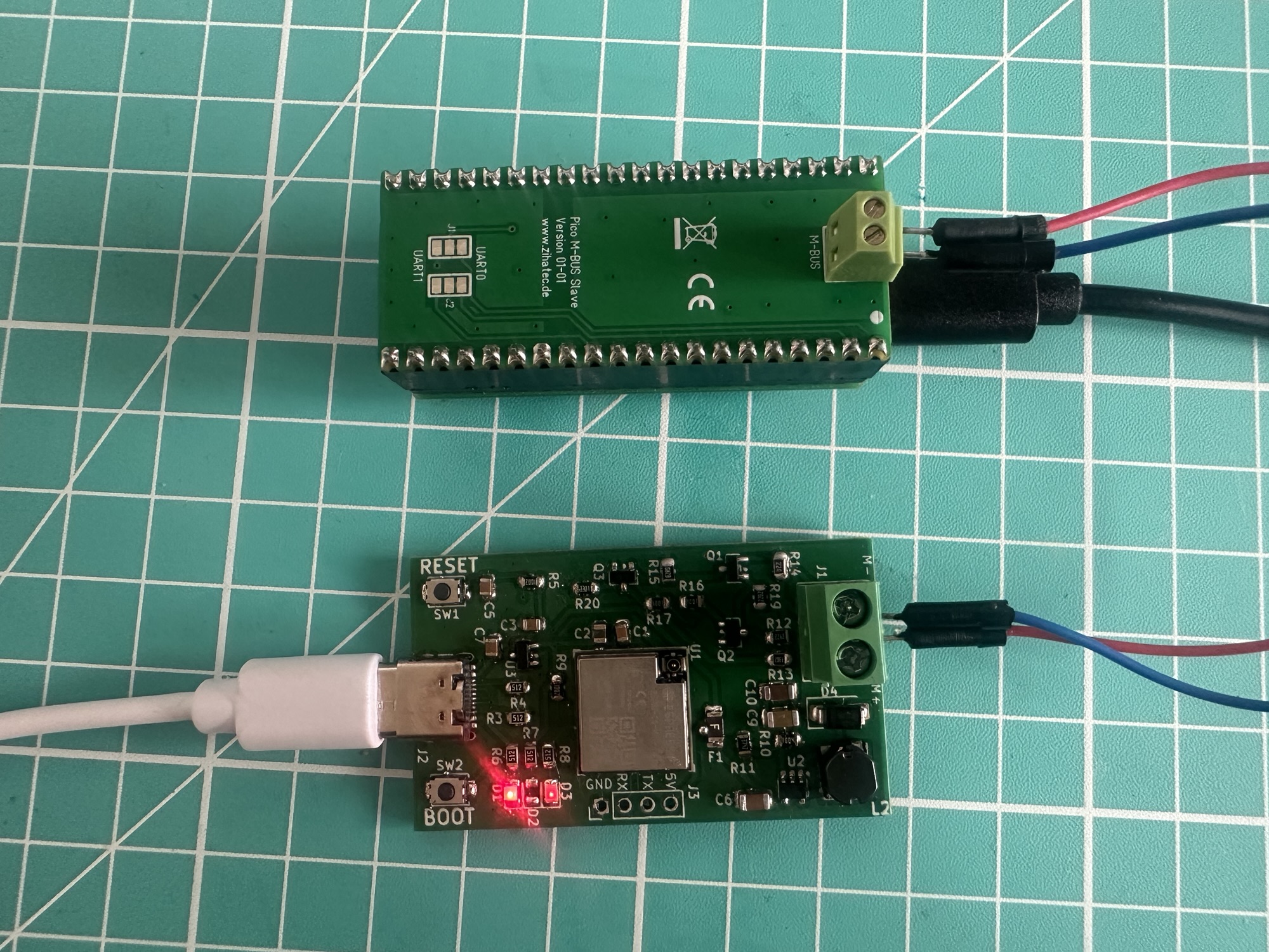
I modified my fireware to just send the initial SND_NKE command. This is part of the MBus protocol, and it’s used to initialise communication between a master and slave. The slave should reply with a single byte 0x5E.
It didn’t.
W (130070) MBus: No ACK from meter at 0x01I (130070) Main: SND_NKE to 0x01 ->> ESP_ERR_TIMEOUTI (132070) MBus: TX SND_NKE: 10 40 01 41 16W (133090) MBus: No ACK from meter at 0x01I (133090) Main: SND_NKE to 0x01 ->> ESP_ERR_TIMEOUTI (135090) MBus: TX SND_NKE: 10 40 01 41 16W (136110) MBus: No ACK from meter at 0x01I (136110) Main: SND_NKE to 0x01 ->> ESP_ERR_TIMEOUTI (138110) MBus: TX SND_NKE: 10 40 01 41 16W (139130) MBus: No ACK from meter at 0x01I (139130) Main: SND_NKE to 0x01 ->> ESP_ERR_TIMEOUT
First thing to check – the address. Each MBus slave must have a unique address on the network. I checked the example code, and the address was defined as 5.
#define MBUS_DEFAULT_ADDRESS 5
I updated my firmware to use 0x05 and tried again…
I (86828) Main: SND_NKE to 0x05 ->> ESP_ERR_TIMEOUTI (88828) MBus: TX SND_NKE: 10 40 05 45 16W (89848) MBus: No ACK from meter at 0x05I (89848) Main: SND_NKE to 0x05 ->> ESP_ERR_TIMEOUTI (91848) MBus: TX SND_NKE: 10 40 05 45 16W (92868) MBus: No ACK from meter at 0x05I (92868) Main: SND_NKE to 0x05 ->> ESP_ERR_TIMEOUTI (94868) MBus: TX SND_NKE: 10 40 05 45 16W (95888) MBus: No ACK from meter at 0x05I (95888) Main: SND_NKE to 0x05 ->> ESP_ERR_TIMEOUT
No luck.
To be honest, I wasn’t expecting it to work first time. I’m not that lucky. On the plus side, my multi-meter showed voltage fluctuations across the M-/M+ terminals, so I figured it was doing something.
Two possible reasons
- My side wasn’t working
- The Pico side wasn’t working
Next, I compared the MBus settings on both sides and noticed the baud rate was only 300 on the PICO side. My firmware was configured to use 2400, which is the MBus default. I bumped the PICO side to 2400 and re-flashed it. I tried again and …
I (607858) Main: SND_NKE to 0x05 ->> ESP_OKI (609858) MBus: TX SND_NKE: 10 40 05 45 16I (610948) MBus: e5I (610948) MBus: ACK (0xE5) received from meter at 0x05I (610948) Main: SND_NKE to 0x05 ->> ESP_OKI (612948) MBus: TX SND_NKE: 10 40 05 45 16I (614038) MBus: e5I (614038) MBus: ACK (0xE5) received from meter at 0x05I (614038) Main: SND_NKE to 0x05 ->> ESP_OKI (616038) MBus: TX SND_NKE: 10 40 05 45 16I (617128) MBus: e5I (617128) MBus: ACK (0xE5) received from meter at 0x05I (617128) Main: SND_NKE to 0x05 ->> ESP_OK
HOLY CRAP. It only started working!!!!
My custom PCB and firmware managed to talk MBus to another device!!
Getting more data!
The handshake worked, which was great, but I couldn’t stop there. I needed to read the data being exposed the meter. The sample Meter had an Encode_Payload() method, which included some values:
payload.addField(MBUS_CODE::BAUDRATE_BPS, 2400); payload.addField(MBUS_CODE::FIRMWARE_VERSION, 25); payload.addField(MBUS_CODE::VOLTS, 10.3); payload.addField(MBUS_CODE::AMPERES, 4.8); payload.addField(MBUS_CODE::POWER_W, 49.44); payload.addField(MBUS_CODE::DIGITAL_INPUT, 5);payload.addField(MBUS_CODE::DIGITAL_OUTPUT, 2);
I tweaked my firmware to parse and log the values returned and, much to my surprise, my code parsed and logged this
I (14220) MBusParser: [0] DIF=02 VIF=FD1C Baud rate = 2400.000000 bps (raw=2400 exp=0)I (14230) MBusParser: [1] DIF=01 VIF=FD0E Firmware version = 25.000000 (raw=25 exp=0)I (14240) MBusParser: [2] DIF=01 VIF=FD48 Voltage = 10.300000 V (raw=103 exp=-1)I (14250) MBusParser: [3] DIF=01 VIF=FD5B Current = 4.800000 A (raw=48 exp=-1)I (14260) MBusParser: [4] DIF=02 VIF=0029 Power = 49.440000 W (raw=4944 exp=-2)I (14270) MBusParser: [5] DIF=01 VIF=FD1B Digital input = 5.000000 (raw=5 exp=0)I (14280) MBusParser: [6] DIF=01 VIF=FD1A Digital output = 2.000000 (raw=2 exp=0)
It seemed like it was working!
Next Steps
The next move is to test my board against a real device: my MBus Heat Meter. At this stage, I’m reasonably confident it will work.
Once I can log some data from a real device, I’ll then test the Matter code and expose my Heat Meter to my heating monitor over Matter!
One thing that still needs addressing is the LDO I’m using – I’m not confident it can supply the juice for the ESP32 to connect to WiFi, but the ESP32-C6 supports Thread, so that should work. Still, I need to actually test it in real life.
The repo is here https://github.com/tomasmcguinness/matter-esp32-mbus-adapter.
If you don’t want to miss the next post, be sure to subscribe!
Did you enjoy this post?
If you found this blog post useful and want to say thanks, you’re welcome to buy me a coffee.
Be sure to check out my YouTube Channel too – https://youtube.com/tomasmcguinness
Thanks,
Tom!

Leave a comment