
My Kronoterm Adapt ASHP is almost installed. In this post, the 2nd part, I continue the (long) journey of getting to this point.
In part 1, I covered the trench, insulated pipes, concrete base and the heat pump itself. In this post, I’ll cover the plant room changes and the control system installation.
Bye, Bye, Boiler!
The first job in the plant room was the removal of the boiler. My big, stupid, oversized boiler.
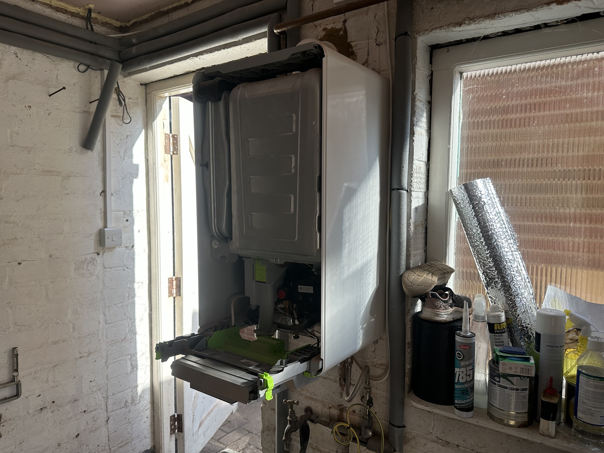
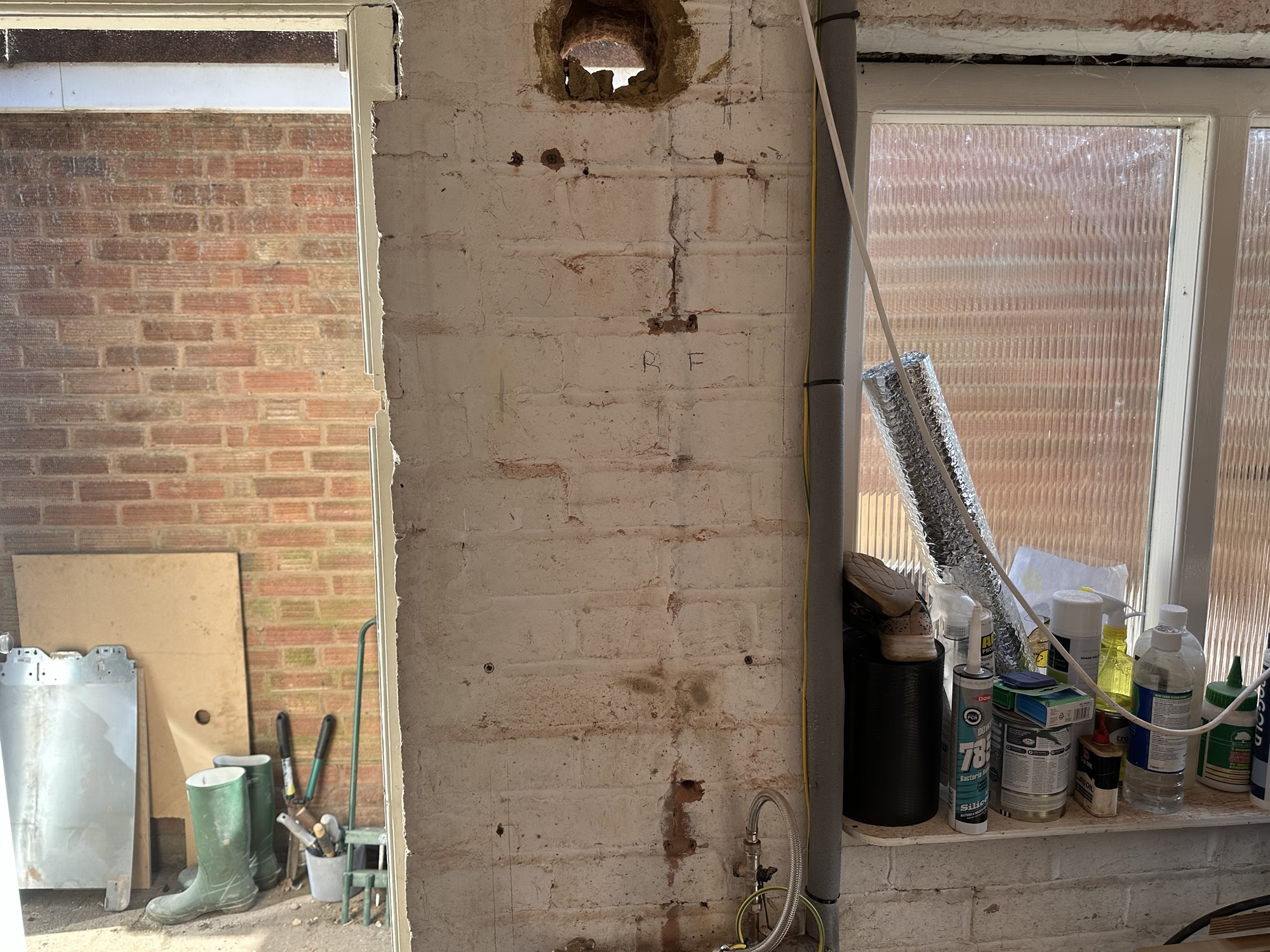
I was glad to see the back of that 35kW monstrosity!
Once I get the gas meter removed, I will start saving 29p a day, which is the current standing charge for gas. That’s about £105 a year.
The Plant Room – Plumbing
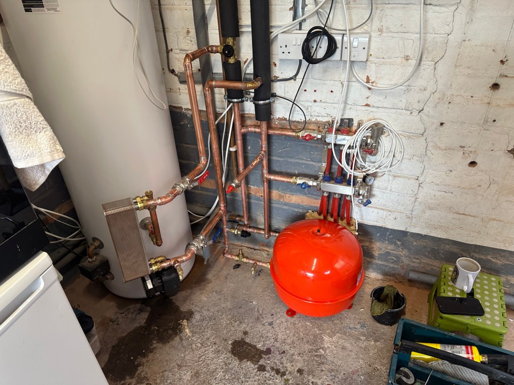
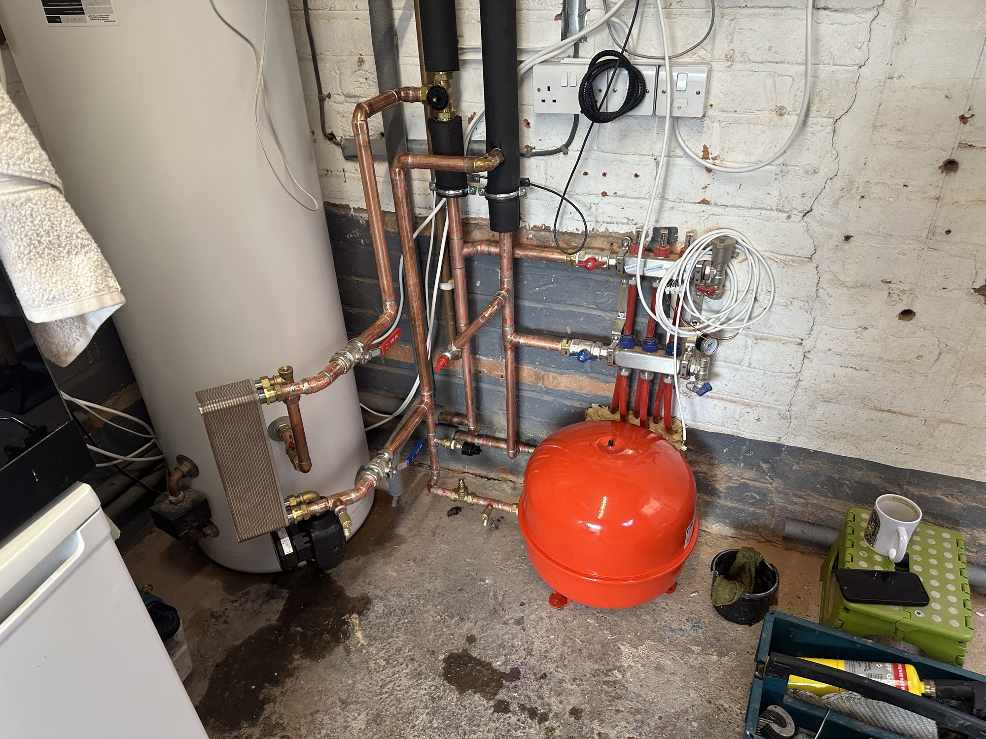
With the boiler gone, the guys started work on the new pipework. Per the design, some of copper needed upgrading from 22mm to 28mm. Better lagging was also required. The first stage was connecting the insulated pipes to 28mm copper.
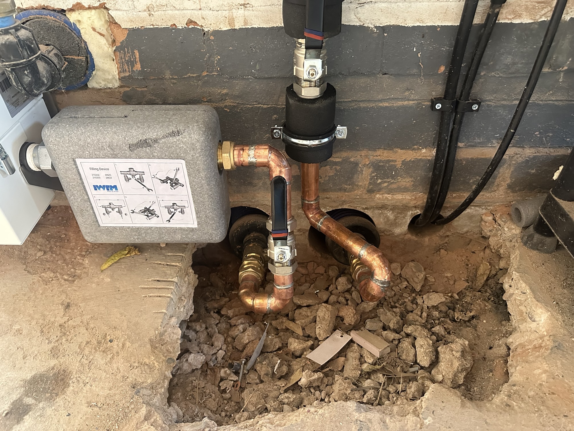
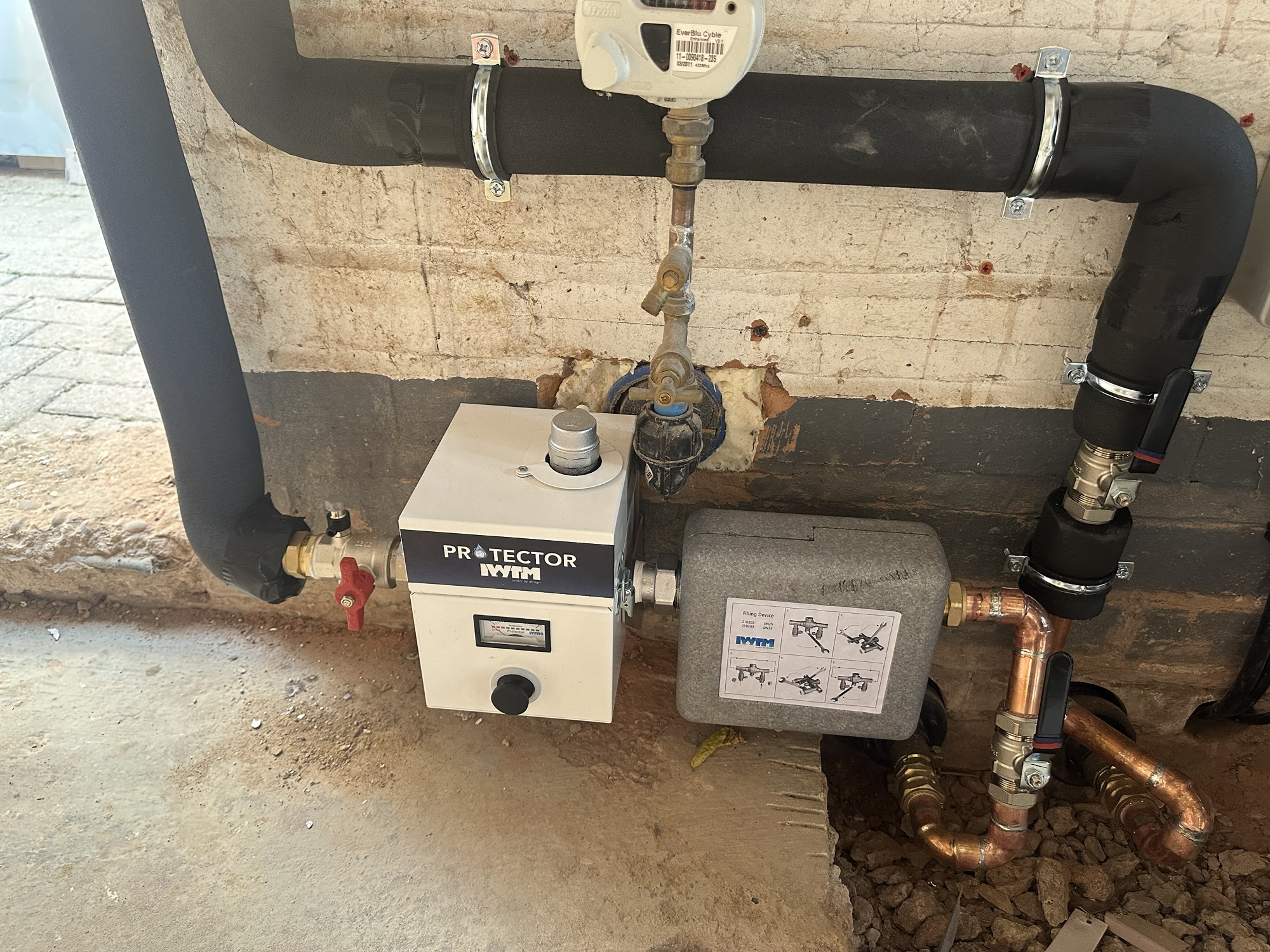
I have to figure out how to make this good. I’ll probably box it off and clean up the concrete edges. I’m not 100% sure what else I can do, but that’s a problem for future Tom.
The 28mm pipes replace the run around the garage wall. My Kamstrup heat meter can be seen in the top right. I’m glad I had this piece of kit and I’m every happier that I ensured it would continue to work with the heat hump. Glyn Hudson at Open Energy Monitor was key to this!
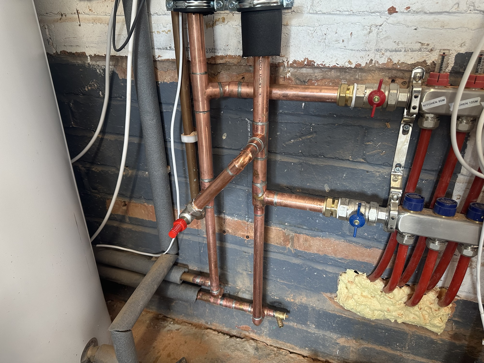
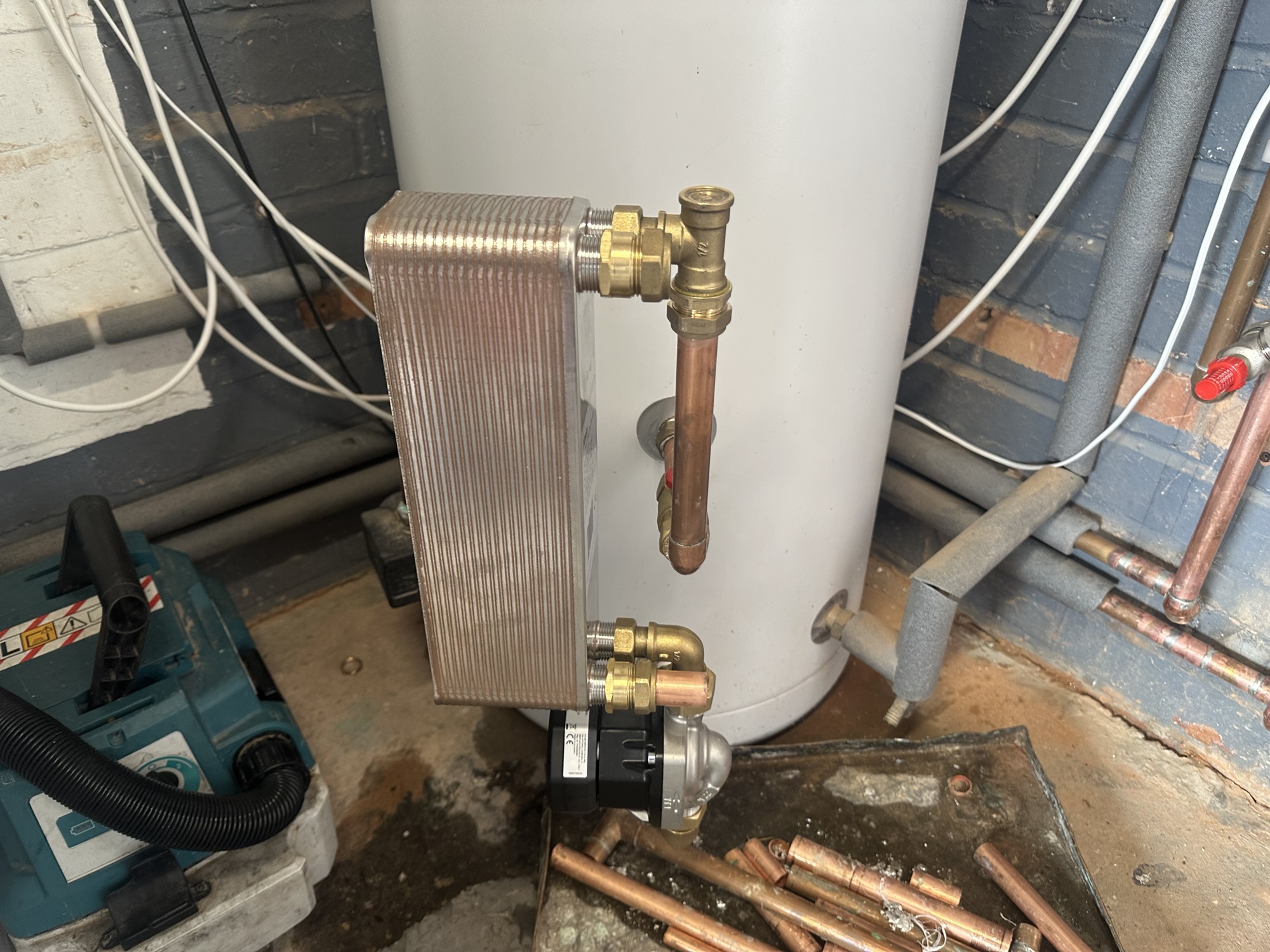
With the 28mm pipe, connections were needed to the UFH manifold and the plate exchanger for the hot water tank.
The last piece of the puzzle was the expansion vessel. A big, hideous, red thing, taking up precious space in my garage 🤣
Plant Room – Control
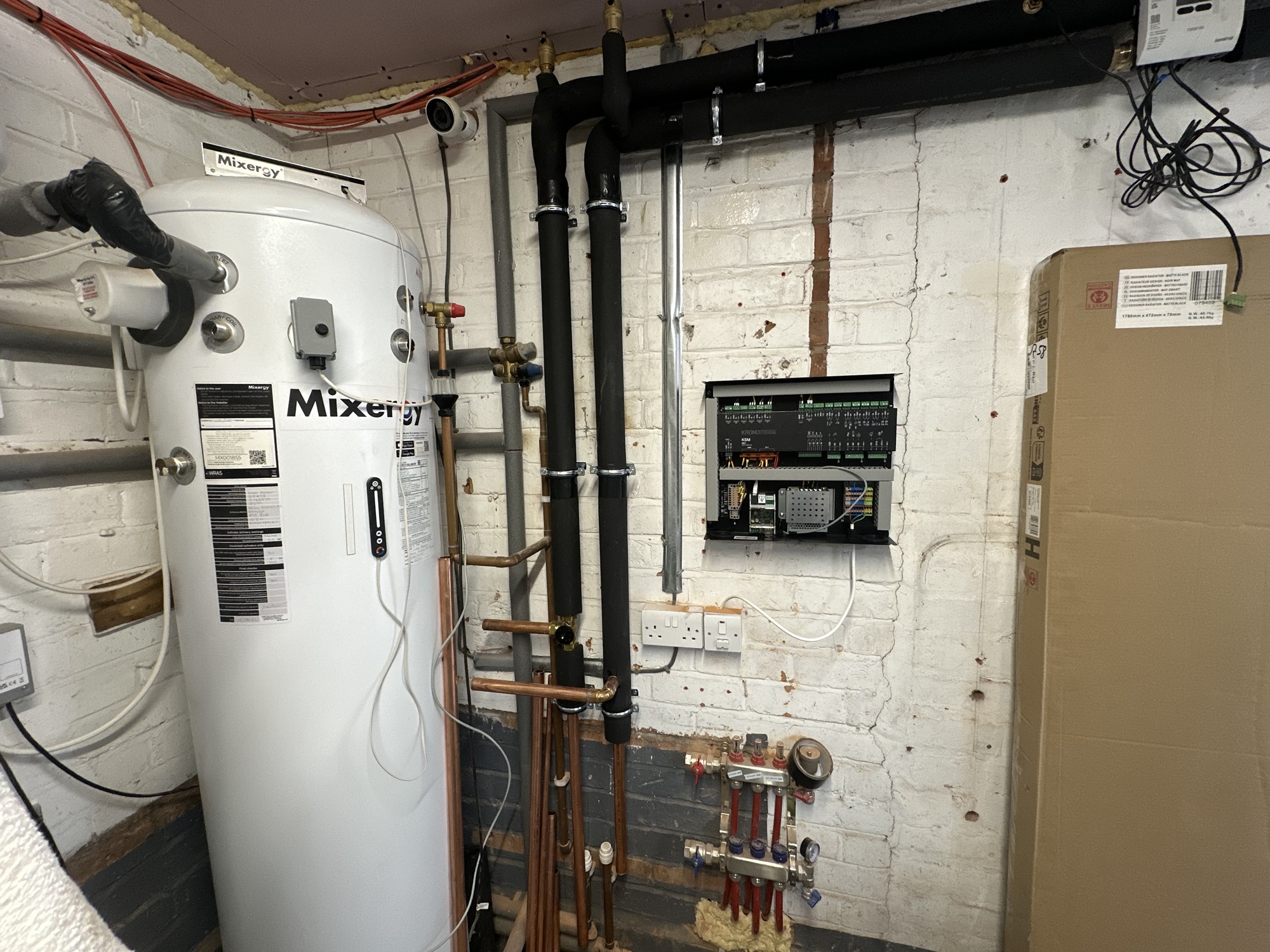
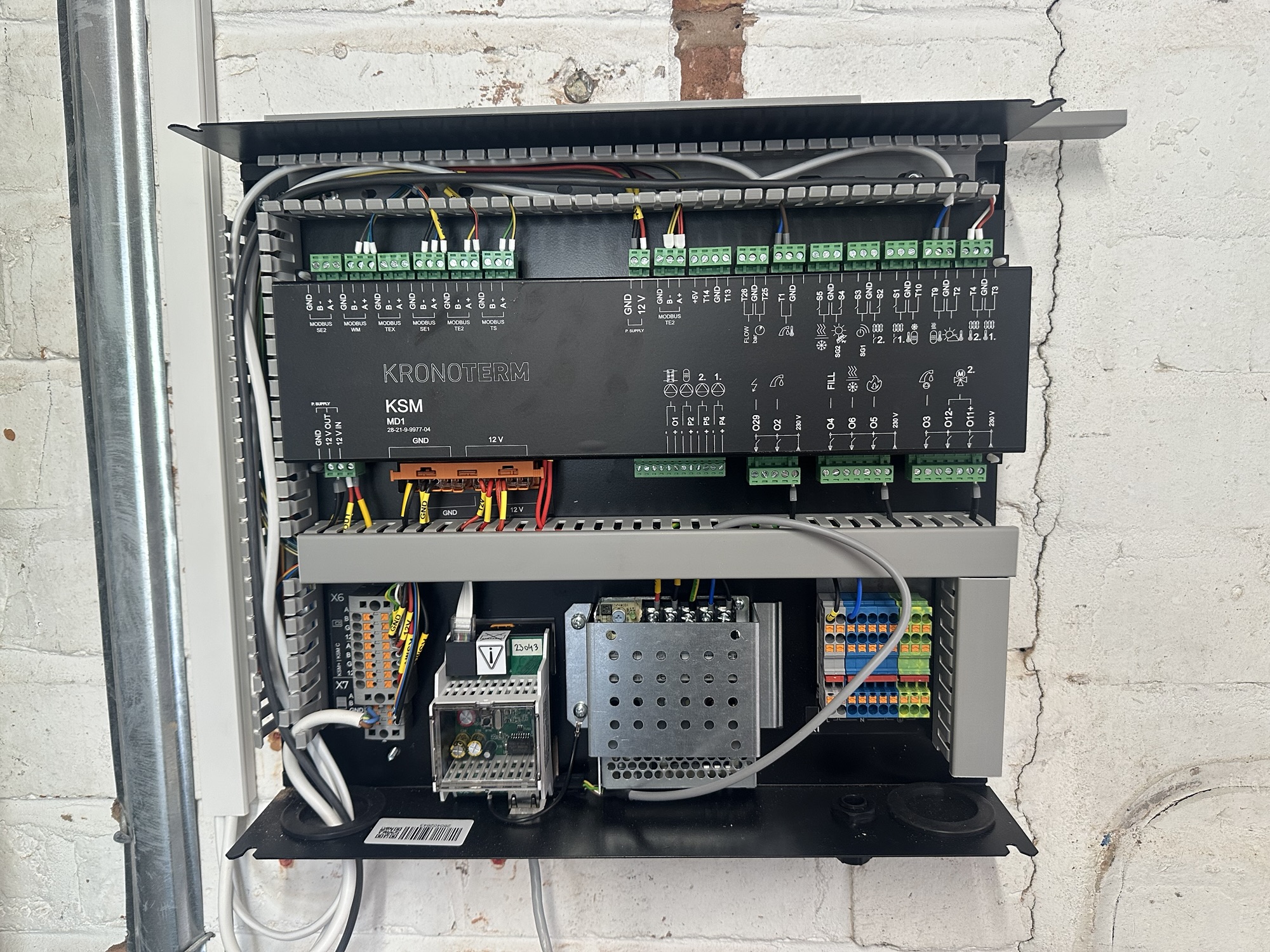
Along with the Adapt heat pump itself, I opted for the Kronoterm Control system. This is the KSM2
This replaces my DIY Home Assistant / Shelly powered boiler control system. Three Shelly 1 relays provided control and enabled PDHW (Priority Domestic Hot Water) on my legacy S-Plan system. A Shelly i3 monitored the call for hot water and a Shelly EM mini measured power consumption.
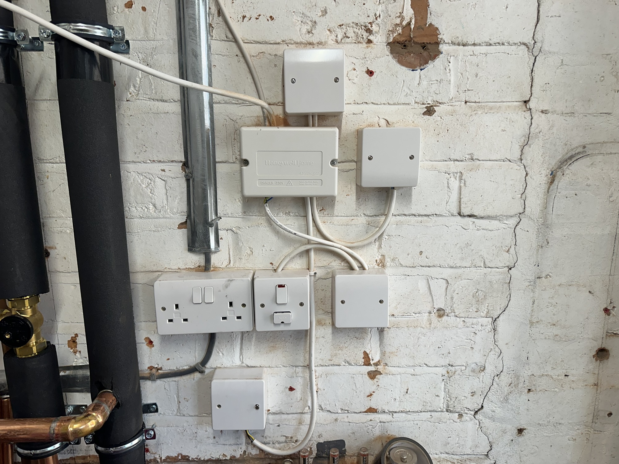
I thought my Shelly system was complex. The KSM2 needed a few more bits and pieces. It’s clearly designed to handle any situation!
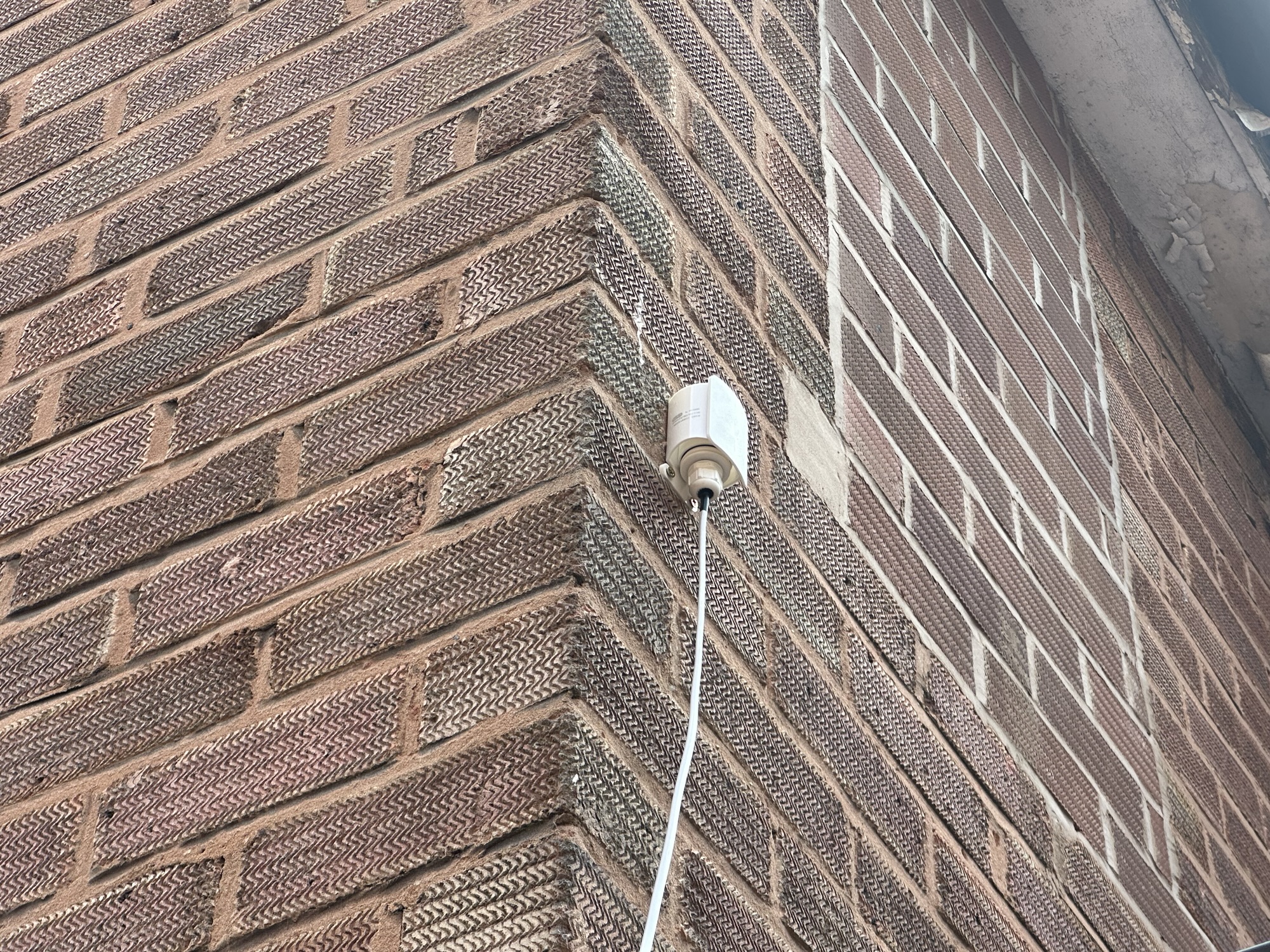
Several sensors were required by the KSM2. A temp sensor on the return, a pressure sensor on the return and an outdoor temperature sensor. The most difficult of these was the outdoor temperature sensor. This is mounted on the north side of the house, shielded from the sun.
The Mixergy HP Integration
Whilst my Mixergy was sold as Heat Pump ready, it required some additional kit. In addition to the plate exchanger, an additional control box was required: the HP Integration MK2. The Mixergy tank was supposedly heat-pump ready. I didn’t realise that meant another £500 in parts.
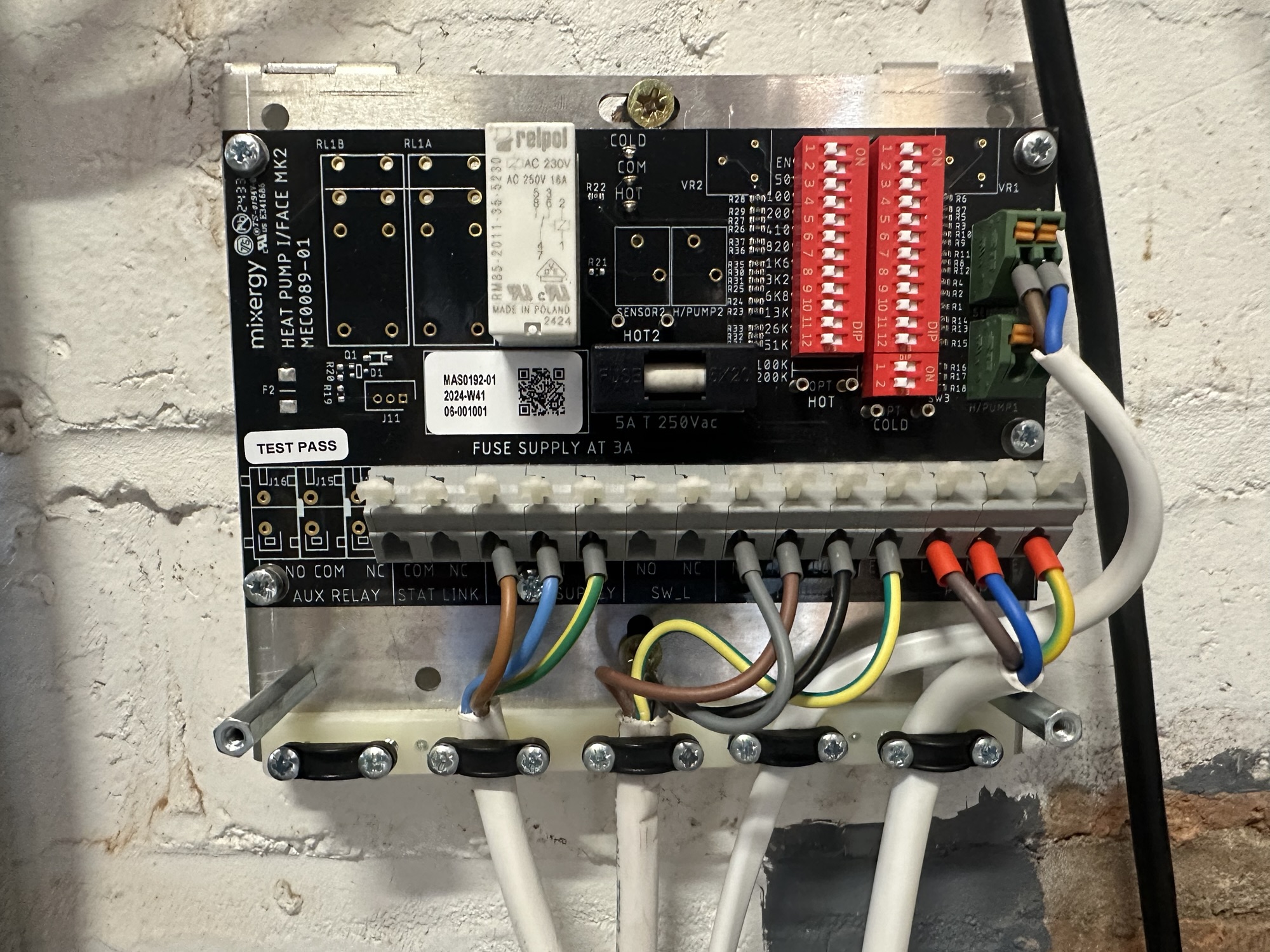
Rather than a direct connection between the Mixergy and the heatpump, this interface board works by “pretending” to be a temperature sensor. When the tank wants hot water, it provides a “cold” temperature reading to the KSM2, which starts a hot water cycle. When it’s done, it sends a “hot” reading.
The red DIP switches let you configure the hot and cold resistance values. Seems overly complicated, but hey ho. As the KSM2 uses PT1000 temperature problems, I followed the DIP switch configuration from Mixergy.
Next Steps
At this point, everything was wired, plumbed and tested.
All I need to do now was wait for my system to be commissioned!
If you don’t want to miss the next update, be sure to subscribe
Did you enjoy this post?
If you found this blog post useful and want to say thanks, you’re welcome to buy me a coffee.
Be sure to check out my YouTube Channel too – https://youtube.com/tomasmcguinness
Thanks,
Tom!

Leave a comment