

This is my Kamstrup Heat Meter. It currently measures how much heat my boiler is producing. It’s been a very useful addition to my heating setup and has featured in some of my videos.
- Introducing my Heat Meter https://youtu.be/0JyeLY9NURg
- Calculating my home’s heat loss using a Heat Meter https://youtu.be/UaoSYYqGLNM
- My big, stupid boiler https://youtu.be/fXhH5aP8vDY
Installed back in October 2023, this little device has been diligently working away.

With the pending installation of my Air Source Heat Pump (😃) I’ve started building my own simple monitoring device (to show status and COP). Because of my obsession with the Matter Smart Home Protocol, I decided to have a go at exposing my heat meter’s data over Matter.
M-Bus Protocol
Like most metering devices, it offers digital access. In the case of this heat meter, that access comes in the form of M-Bus, or Meter Bus (not to be confused with ModBus!)
When I bought this heat meter from Open Energy Monitor, they supplied a simple M-Bus to USB adapter, which allows me to read the meter’s dataMB using a Raspberry Pi. M-Bus is a two-wire protocol and runs on a nominal voltage of 36V. This adapter handles the power conversion and signalling, outputting a binary stream over UART.

If you watch my introduction video, I show how I read that stream and expose the data over MQTT. The MQTT that my Python script publishes looks like this:
{ "MBusData": { "SlaveInformation": { "Id": "72836166", "Manufacturer": "KAM", "Version": "52", "ProductName": null, "Medium": "Heat: Outlet", "AccessNumber": "57", "Status": "10", "Signature": "0000" }, "DataRecord": [ { "_id": "0", "Function": "Instantaneous value", "StorageNumber": "0", "Unit": "Energy (kWh)", "Value": "49545", "Timestamp": "2026-07-08T08:12:03Z" }, { "_id": "13", "Function": "Instantaneous value", "StorageNumber": "0", "Unit": "Volume flow (m m^3/h)", "Value": "0", "Timestamp": "2026-07-08T08:12:03Z" }, [...TRUNCATED...] ] }}
This has worked flawlessly for me over the last three years so I can’t complain. It does, however, involve a Raspberry Pi, a PoE adapter, a python script and an MQTT server. This is all trivial when you know what you’re doing, but there are a fair number of moving parts.
I want my monitor to just use Matter, so I need my Heat Meter to talk Matter too.
Moving to Matter
My initial plan was to use matter.js running on the existing Pi, but after some reflection, I decided to look at this as a custom hardware opportunity. If I could build my own adapter, I could remove the Raspberry Pi complete and repurpose it.
What I needed was a PCB with an ESP32 and the hardware to connect to an M-Bus device.
I was pretty happy with the ESP32 part of this. I decided to use the ESP32-C6 variant, as this one supports both WiFi and 802.15.4, which is the radio for Zigbee and Thread. This would give the board utility beyond just Matter. Since I had built my own dev board for the ESP32-H2, I was comfortable on what was needed on that front.

As ever, the open-source community provided me with a great springboard. I found several projects related to M-Bus and UART. The first page I found was this M-Bus UART converter | TaaraLabs and this led me to libmbus/hardware at master · rscada/libmbus

From studying the schematics, there were two components I needed for M-Bus
- Something to convert the 5V DC supplied by USB to the 36V DC required by M-Bus
- Something to convert 3.3V DC UART signals to 36V DC signals and vice-versa
The Schematic
I ended up just adding these new sections to a copy of my existing H2 schematic, starting with the power adapter.

I’ll be honest – I don’t 100% know how this works, but it steps 5V up to 36V using an AP3015.
The second section was the level shifter, which converts from 36V to 3V and from 3V back to 36V. I mostly understand how this works! The two pairs of voltage dividers dictate the conversion with the help of MOSFETS.

The reset of the schematic remained pretty much the same, changing just the MCU from an ESP32-H2-MINI-1 to an ESP32-C6-MINI-1U. In addition to switching variant, I also opted for the module with an external antenna. I hoped this would help reduce any interference from the other parts of the circuit.
Another thing I tried this time was to use a BOM (or Bill of Materials).
In KiCad, I added a Mouse_PN (typo!) to each sysmbol and then add the Mouser part number like this:

I could then use the KiCad option “Generate Bill Of Materials” to create a CSV.

Mouser then let me *upload* the CSV and it populated my cart automatically! I wish I had learned this flow sooner. If this board worked, it would make re-ordering the same parts much, much easier!
The PCB
Turning the schematic into PCB took me a quite a few hours and a few attempts. I’m relatively new to PCB design and I’d never tackled this many components before. I even added some diagnostics to the top right, which should allow me to listen to the UART0 of the ESP32.

I left the same three indicator LEDs as I had before. 5V, 3.3V and one connected to a GPIO. This lets me run the blink sketch to ensure everything is okay.
To have them fabricated, I chose PCBWay this time, instead of Aisler. Amazingly easy process as they offer a KiCad tool that uploads the board directly. I ordered on a Friday, and the boards were in my hand on Wednesday! The initial $5 coupon I had meant the boards were free and I paid just the postage, which was $22.
If you want to sign up to PCBWay, use my referral and you’ll get $5 of free credit – https://pcbway.com/g/a501i1

First Mistake
No sooner had I sent the PCB for fabrication, then I realised the LDO I’d chosen, the MCP1700-3300, wasn’t powerful enough. The H2 only needed about 120mA for BLE and 802.15.4. The C6 needs much more. In fact, I don’t think the MCP1700-3300 will drive the WiFi!
Not a big deal really as I can use Thread. I will look into replacing the LDO with a different model, one with the same SOT-23 footprint.
Second Mistake (15th July)
This one was more painful. I put Q1 the wrong way around, with the emitter and collector flipped! It should be
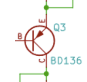
but mine was
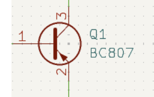
Not insurmountable, but would require some jumper wires.
First Test (20th July)
After messing up my Mouser order and only ordering 1/3 of the parts (🤬), I decided to solder up the ESP32-C6 components anyway. I had some from over dev board. Thankfully, the ESP32 booted and I connected over USB. I was able to put on the classic *Blink* example.
Third Mistake (22nd July)
Even though I had the Q1 MOSFET the wrong way around, I decided to try the voltage booster circuit. Unfortunately, after soldering everything on, I found another mistake!
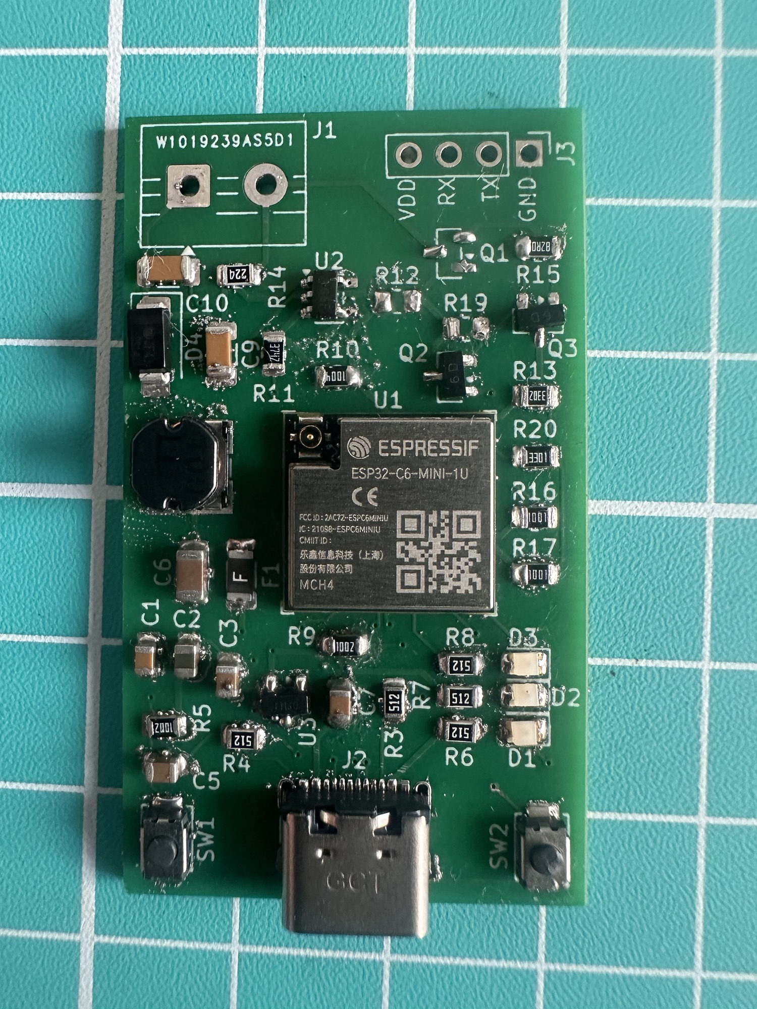
I had a junction in the wrong place!
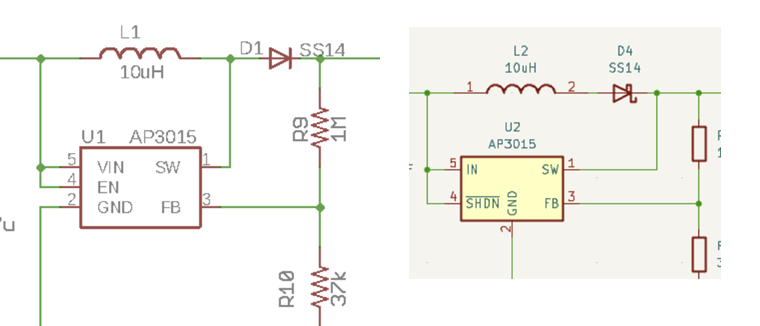
The Switch input of the AP3015 should be taken between the inductor and the diode. In my schematic, I had it after. After some help from Claude, I understood why this was a problem. It didn’t allow a build-up of charge in the inductor inductor’s current doesn’t change.
The Firmware
The firmware is based on the esp-idf and esp-matter SDKs, both from espressif.
Unfortunately, Matter doesn’t have the concept of a Heat Meter, which is a shame. This meant I needed to cobble together a custom Device Type. Thankfully, Matter allows this with the use of Vendor Prefixes.
I defined a new cluster, made up of flow rate, the flow and return temperatures and the calculated power.
Each of these values was defined as a custom attribute, part of the new cluster.
#define HM_ATTR_FLOW_ID 0x0000u // float, m^3/h#define HM_ATTR_FLOW_TEMP_ID 0x0003u // int32, 0.01 degC#define HM_ATTR_RETURN_TEMP_ID 0x0004u // int32, 0.01 degC#define HM_ATTR_POWER_ID 0x0005u // int64, mW
The rest of the code is boilerplate. It sets up the UART driver and then writes and reads the registers via M-BUS, putting the values into my custom attributes.
I might make a request to the CSA to add heat meters as a device type.
Next Steps
I’m still waiting on the remaining parts from Mouser and once I have them, I’ll be attempting some assembly and testing of the MBus parts. I’ll be sure to post an update either way.
I’ve also revised my PCB and I’ll be ordering an updated batch from PCBWay.
Once I’ve gotten everything working, I’ll make everything available on Github (code and hardware)
If you don’t want to miss the post, be sure to subscribe
Did you enjoy this post?
If you found this blog post useful and want to say thanks, you’re welcome to buy me a coffee.
Be sure to check out my YouTube Channel too – https://youtube.com/tomasmcguinness
Thanks,
Tom!


Leave a comment