
After my success with my MBus adapter PCB, I finally got the push I needed to finish the next version of Dual Temperature Sensor. I sent it off to PCBWay for manufacture!
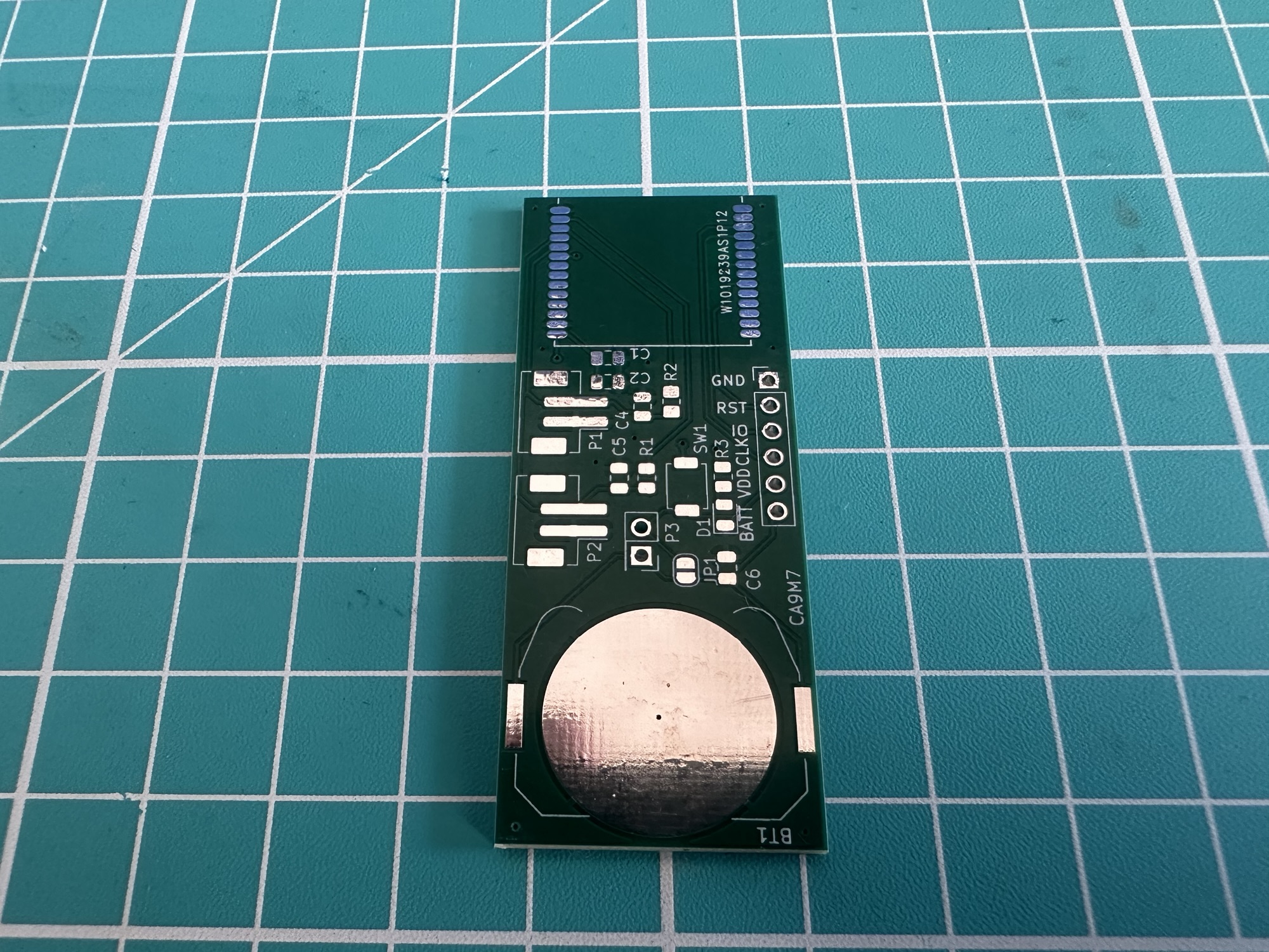
This version had two important changes:
- I remove the LDO so the nRF54 would be powered *directly* by a 2032 coin cell
- I repositioned the button to fix the issue with waking the device from sleep.
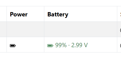
In this previous post, I added the Power Source cluster to my firmware, so the device could report its power level. What I didn’t do was actually read the battery level. I had struggled to get my head around this. After taking a break from the project for a while, I had a clearer approach when I returned to it.
In this post, I’m going to look at how I measure the battery.
Measuring Power
In my first version of the sensor, I was using a low power LDO to provide a steady 1.8V. This allowed me to power the sensor from both USB (5V) and larger LiPO batteries (4.7V). My goal, however, was always something neat and tidy, something that could be easily hidden. Not something with a massive battery hanging off it or a USB block plugged into the wall!
When it came to measuring the battery, I felt confused. As the LDO provided steady power, I couldn’t use that. I needed to read the battery voltage in another way. The obvious answer was a voltage divider connected to an ADC pin.
However, after a lot of reading, I came across several projects that just connected the battery directly to the nRF itself. A typical 2032 coin-cell battery has a max voltage of 3.3V, which is within the max 3.6V of the nRF54.
Powering it directly gave two advantages
- Less components (no LDO and no decoupling capacitors)
- I could use the battery voltage directly within the ADC (no additional traces needed on the PCB)
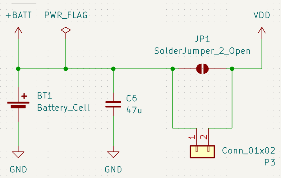
My research indicated a buffer capacitor would be helpful, and I also added a header pin and solder jumper, so I could measure power consumption with my PPKII
With the power coming in directly, I had to configure an ADC pin to read the VDD. This is done using NRF_SAADC_VDD
channel@0 { reg = <0>; zephyr,gain = "ADC_GAIN_1_4"; zephyr,reference = "ADC_REF_INTERNAL"; zephyr,acquisition-time = <ADC_ACQ_TIME_DEFAULT>; zephyr,input-positive = <NRF_SAADC_VDD>; zephyr,resolution = <12>; zephyr,oversampling = <8>;};
Using this value followed the boiler place ADC code.
int err = adc_sequence_init_dt(&sAdc, &sAdcSequence);if (err < 0) { LOG_ERR("Could not initialise the battery ADC sequence (%d)", err); return err;}err = adc_read_dt(&sAdc, &sAdcSequence);if (err < 0) { LOG_ERR("Could not read the battery ADC (%d)", err); return err;}int32_t voltageMv = static_cast<int32_t>(sAdcBuffer);err = adc_raw_to_millivolts_dt(&sAdc, &voltageMv);if (err < 0) { LOG_ERR("Battery value in mV not available (%d)", err); return err;}return voltageMv;
I wired this voltage reading into the Matter Power Source cluster that I already had.
Testing it out
As I was no longer had an LDO on the board, I couldn’t use the 5V supplied by my J-Link. It would fry the chip. I dusted off my bench supply and hooked it up.
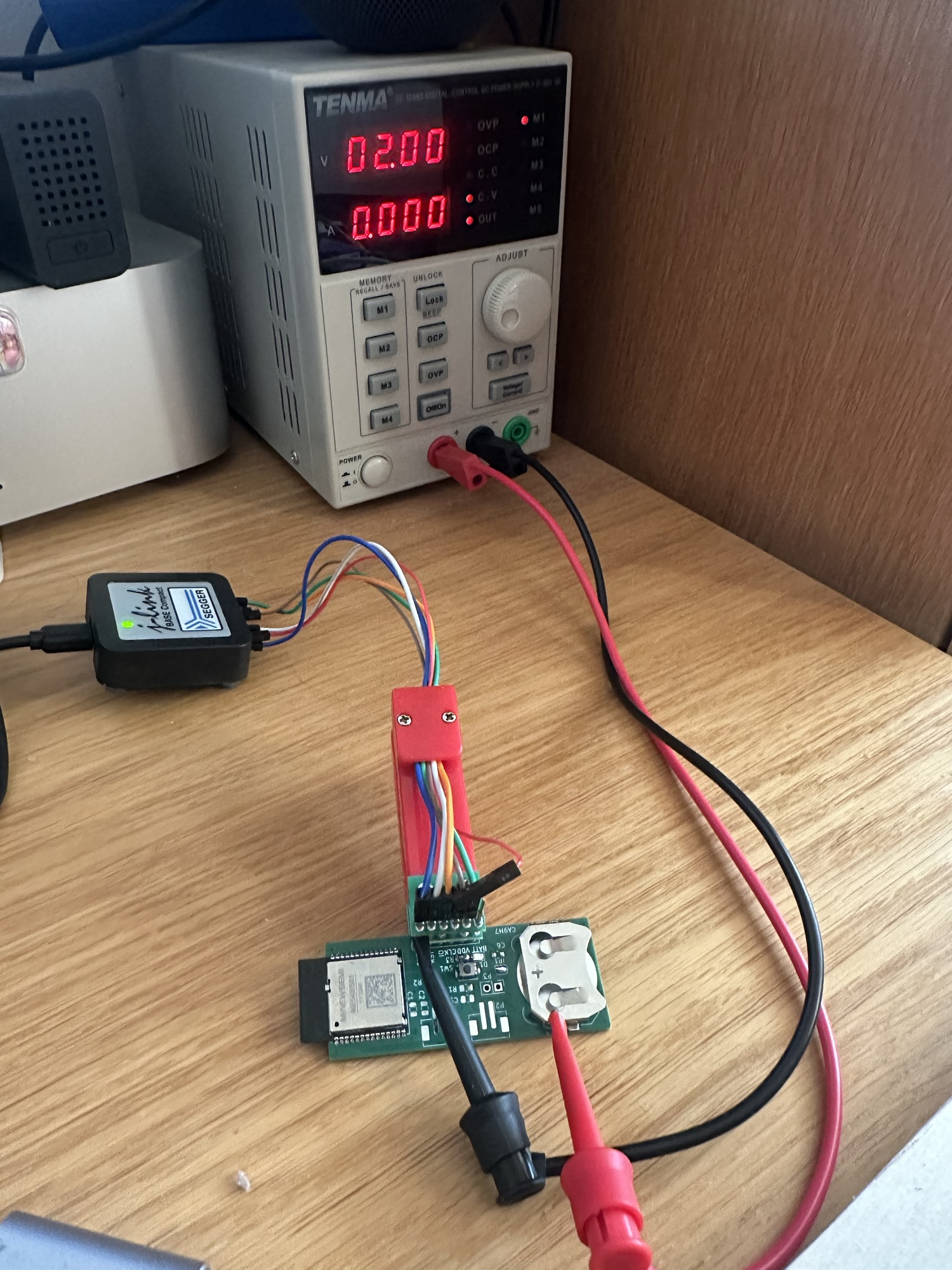
On the board side, I had Claude put together a basic firmware version that took battery measurements and expose them over Matter.
With the firmware installed and board powered up, I needed to commission it so I could read the Matter values. I did this using the trusty chip-tool and paired the device as node 0x70.
chip-tool pairing code-thread 0x70 hex:<dataset> 3497-011-2332 --bypass-attestation-verifier true
With pairing complete, I needed to read the attributes. The Power Source cluster provides a few relevant attributes when the Battery feature is enabled

I used the chip-tool to query the voltage
chip-tool powersource read bat-voltage 0x70 0x00
Voltage came back as 1997, which is 1.997V

Not bad at 99.9% accuracy!
I upped the bench supply to 3V and tried again. This time it reported 2997.

I consider that a success!
Percentage?
In addition to the battery voltage, there is a Battery Percentage remaining. This is the one that is of the most practical use, but I need to get a handle on the discharge curve of 2032 coin cell battery first.
Next Steps
I’m thrilled this worked and annoyed I didn’t think of direct battery power sooner. I’m sure there are downsides and I need to consider what happens when the battery’s output drops too low. Will the sensor kinda work? Will radio use causes brownouts?
These are things I’ll work on. For now, my new board and approach to the battery is working! I will need to desolder all the existing boards and move the components over to the new boards. I don’t want to waste a lot of perfectly good Minewsemi modules.
Once I’ve assembled a full board, I’ll do a post here and probably make a YouTube video on it.
If you don’t want to miss the next update, be sure to subscribe!
Did you enjoy this post?
If you found this blog post useful and want to say thanks, you’re welcome to buy me a coffee.
Be sure to check out my YouTube Channel too – https://youtube.com/tomasmcguinness
Thanks,
Tom!

Leave a Reply