
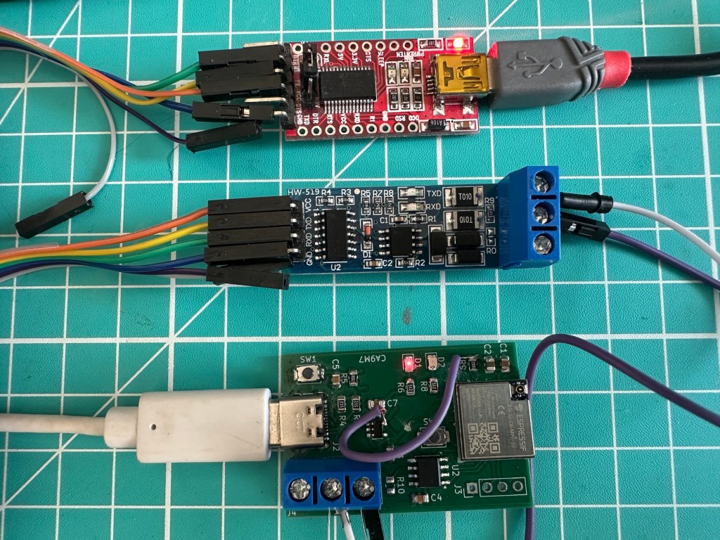
After ironing out the issues with my Modbus ESP32 Adapter board, the next stage was to test it worked.
When testing stuff like this, I find it helps to have a known *working* reference. To implement this, I put together a simple test. First, I used a YP-05 USB to UART adapter, which was connected to a HW-519 UART to Modbus adapter. The HW-519 then had its A & B wires connected to my PCB
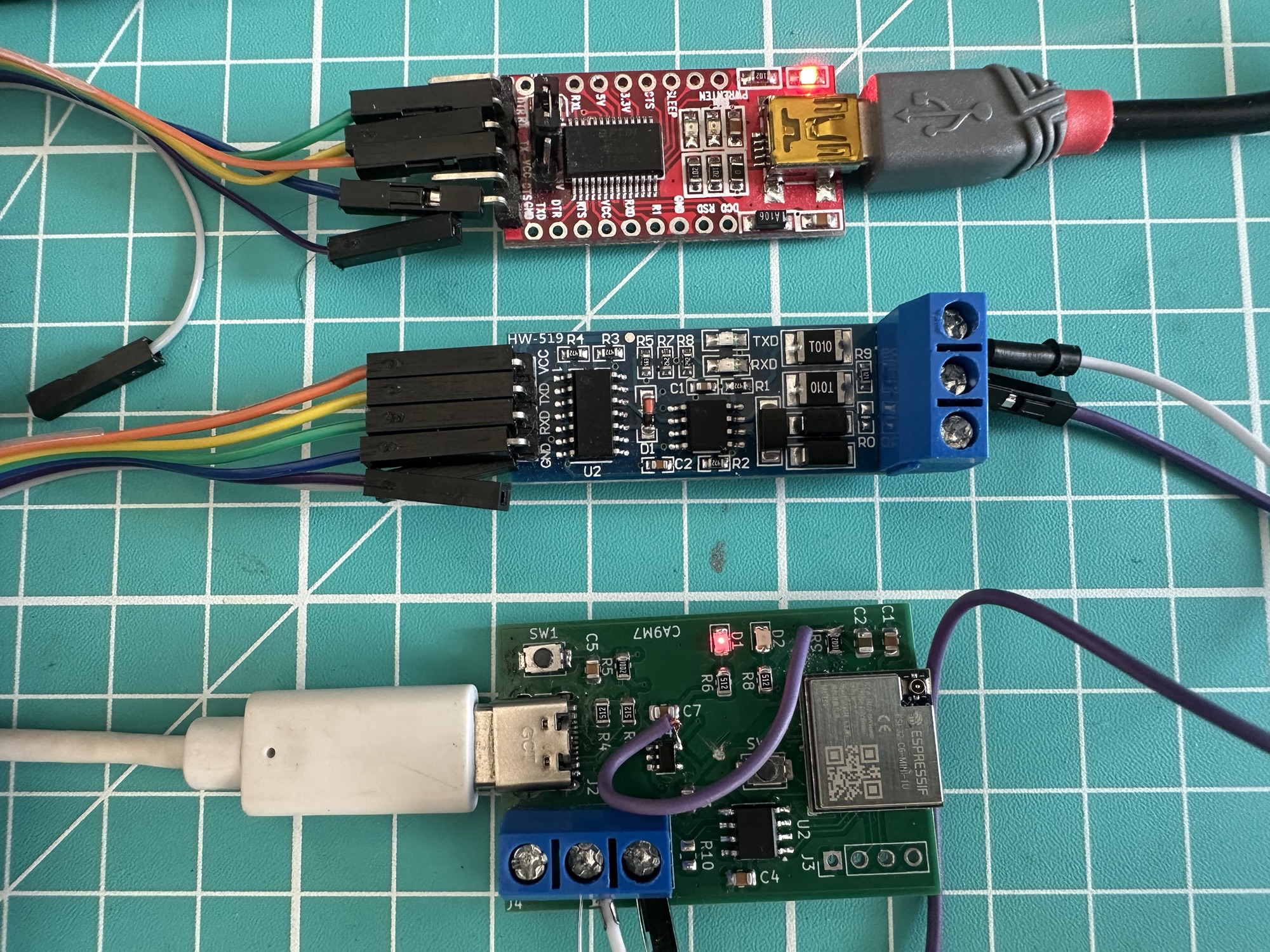
Testing the send (TX)
First thing I decided to try was to send a single byte from my PCB. I added some code to my firmware, which would just send one byte, every second.
I (557486) Modbus: TX 0x55I (558486) Modbus: TX 0x55I (559486) Modbus: TX 0x55I (560486) Modbus: TX 0x55I (561486) Modbus: TX 0x55I (562486) Modbus: TX 0x55I (563486) Modbus: TX 0x55I (564486) Modbus: TX 0x55I (565486) Modbus: TX 0x55I (566486) Modbus: TX 0x55
On my PC, I had Claude create a simple Python script called receive_byte.py, which would open a connection to my YP-05 and log any bytes received. After a little tinkering, I discovered, to my annoyance, that my wiring was wrong.
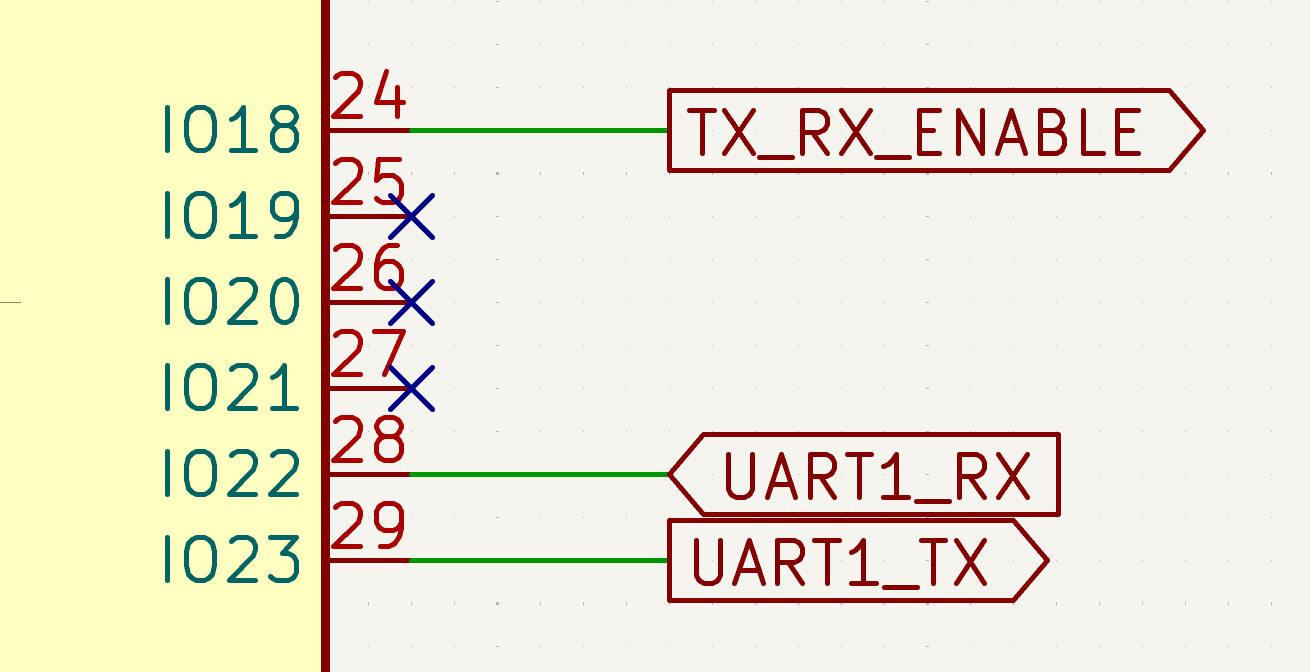
I had my UART1 GPIOs the wrong way around. Thankfully, as this is all software defined, I just swapped the #defines in my firmware. TX to GPIO22 and RX to GPIO23. I dodged a bullet there. I made a note to update my firmware labels.
#define MODBUS_UART UART_NUM_1#define TXD_PIN ((gpio_num_t)22)#define RXD_PIN ((gpio_num_t)23)#define DE_RE_PIN ((gpio_num_t)18)#define MODBUS_SLAVE_ADDR 1
With both sides running, the Python script started to log the byte it was receiving!
[08:35:13] Received byte 0x55[08:35:14] Received byte 0x55[08:35:15] Received byte 0x55
I changed the firmware value to be sure
[08:41:34] Received byte 0x48[08:41:35] Received byte 0x48[08:41:36] Received byte 0x48
Amazing. My PCB was sending a byte over Modbus!
Testing receive (RX)
I fired up the inverse python script send_byte.py and put my firmware into the receive node. The python script started sending a byte
[08:55:21] Sent byte 0x55[08:55:22] Sent byte 0x55[08:55:23] Sent byte 0x55
Unfortunately, my firmware reporting nothing
W (31516) Modbus: RX idle (no bytes in 2000 ms)W (33516) Modbus: RX idle (no bytes in 2000 ms)W (35516) Modbus: RX idle (no bytes in 2000 ms)
After it ran for 30 seconds or so, I had a few of these messages:
I (120826) Modbus: RX 0x00 (0b00000000)I (120836) Modbus: RX 0x00 (0b00000000)I (120836) Modbus: RX 0x00 (0b00000000)
It had received something, just not what I wanted.
After a short diagnostics session with Claude, it suggested that I was missing a pull-up and pull-down resistor across the A & B terminals. I added 330Ω between B and GND and 330Ω between A and the 3V3 pin on the MAX3845.
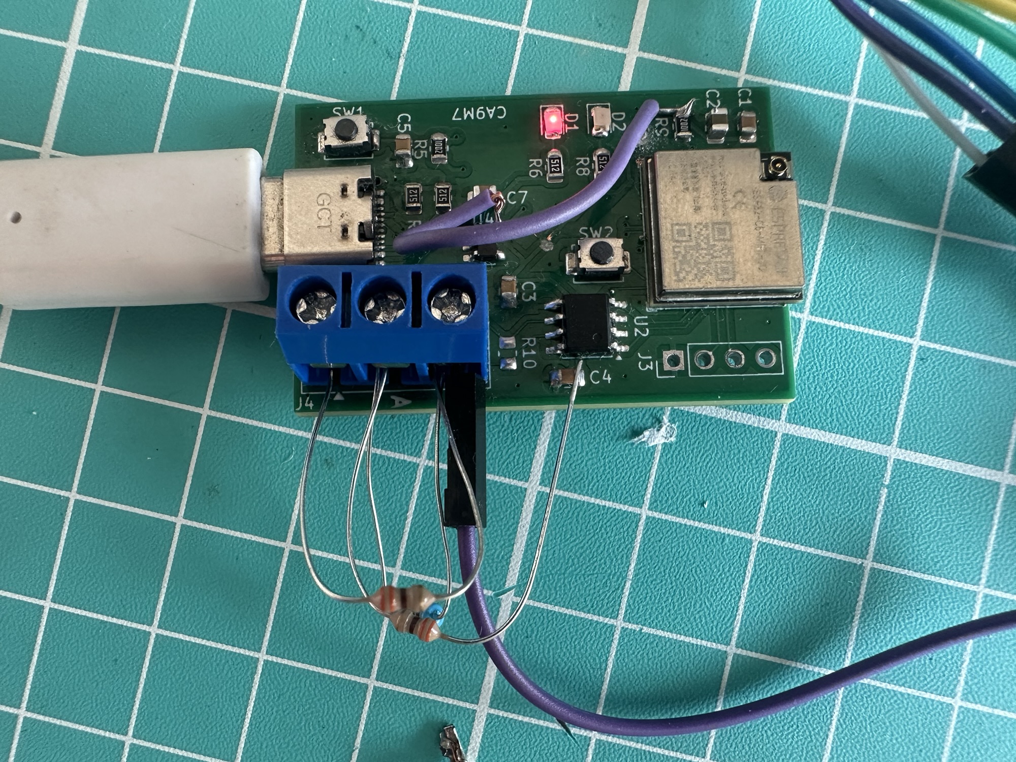
As soon as I touched the resistor to the 3V3 pin, the logging confirmed the data was flowing in!
I (74026) Modbus: RX 0x55 (0b01010101)I (75026) Modbus: RX 0x55 (0b01010101)I (76026) Modbus: RX 0x55 (0b01010101)I (77026) Modbus: RX 0x55 (0b01010101)
Claude suggested I only needed the bias resistors because I was using the HW-519, which had an auto-detect mechanism. This was sort of confirmed by the fact I had a MAX485 talk to an SDM120M meter without the bias resistors.
Something more complicated
Sending and receiving one byte is a good start, but hardly sufficient for a real-world application.
To give me something more substantial to test, I turned to the pymodbus library. This particular library is great because it has a simulator, which you can configure using JSON files. I had Claude whip me up a configuration based on the SDM120M electricity meter. Like the send_byte and receive_byte python scripts, this used the same YP-05 and HW-519 setup.
I put my custom firmware onto the PCB, setting it o its original operation (reading from the SDM120M) and tried it out. With the bias resistors in place, the communication worked perfectly!
I (3545608) SDM120M: Reading SDM120M...I (3545608) Modbus: Requesting reg 0x0000I (3545608) Modbus: 01 04 00 00 00 02 71 cbI (3545658) Modbus: Received 9 bytesI (3545658) Modbus: 01 04 04 43 66 80 00 6f dfI (3545658) Modbus: reg 0x0000 = 230.500000I (3545658) SDM120M: Voltage: 230.50 VI (3545658) Modbus: Requesting reg 0x0006I (3545668) Modbus: 01 04 00 06 00 02 91 caI (3545718) Modbus: Received 9 bytesI (3545718) Modbus: 01 04 04 3f 9d 70 a4 42 05I (3545718) Modbus: reg 0x0006 = 1.230000I (3545718) SDM120M: Current: 1.23 AI (3545728) Modbus: Requesting reg 0x000CI (3545728) Modbus: 01 04 00 0c 00 02 b1 c8I (3545778) Modbus: Received 9 bytesI (3545778) Modbus: 01 04 04 43 8d 99 9a 94 10I (3545778) Modbus: reg 0x000C = 283.200012I (3545778) SDM120M: Active Power: 283.20 WI (3545788) Modbus: Requesting reg 0x001AI (3545788) Modbus: 01 04 00 1a 00 02 50 0cI (3545828) Modbus: Received 9 bytesI (3545828) Modbus: 01 04 04 41 45 70 a4 da 16I (3545828) Modbus: reg 0x001A = 12.340000I (3545828) SDM120M: Total Energy: 12.34 kWh
The next step was to test the board with an actual SDM120M. Thankfully, I had one installed and waiting. It’s almost like I knew 🤣
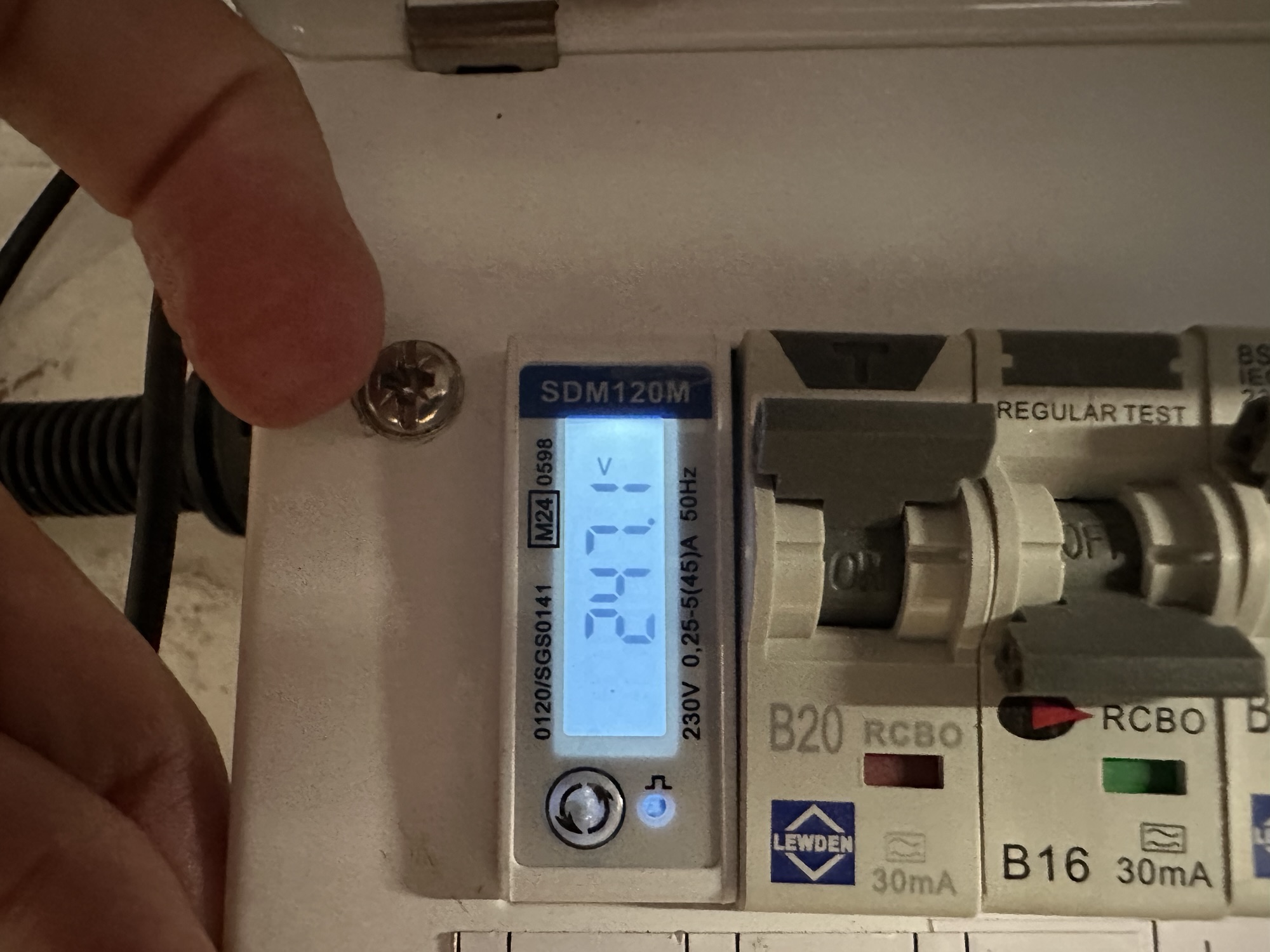
When the electrician added the circuit for my new heat pump, I had him include an SDM120M, which is a certified electricity meter. This would allow me to measure how much power my heat pump was drawing.
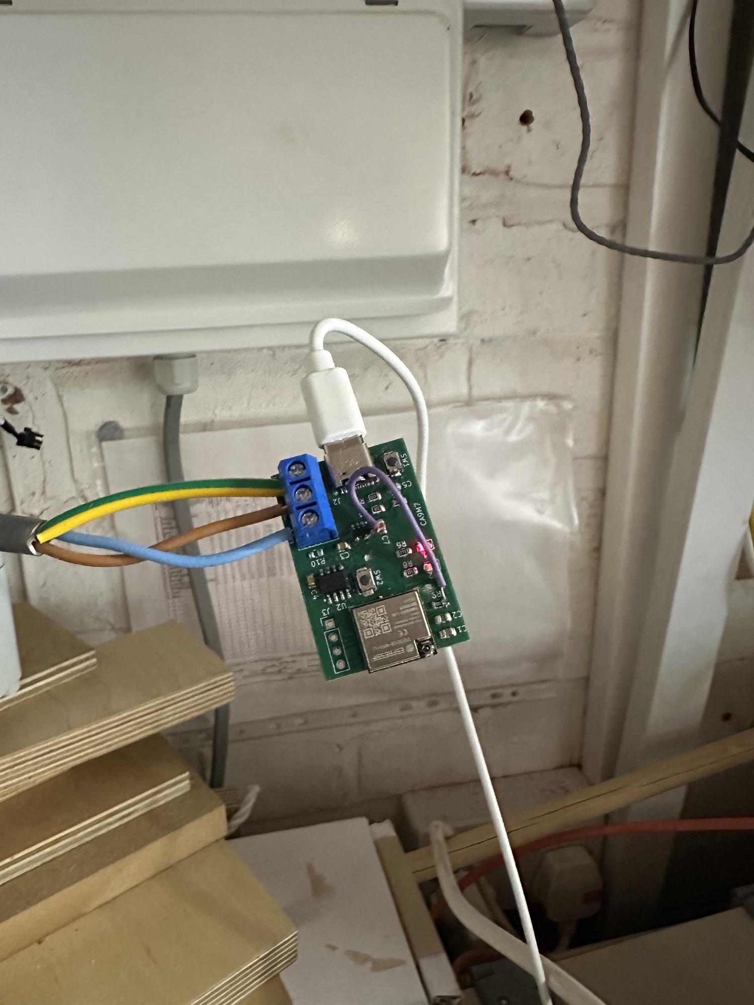
I paired the sensor with my Heating Monitor and, after swapping A & B, it started to send readings!
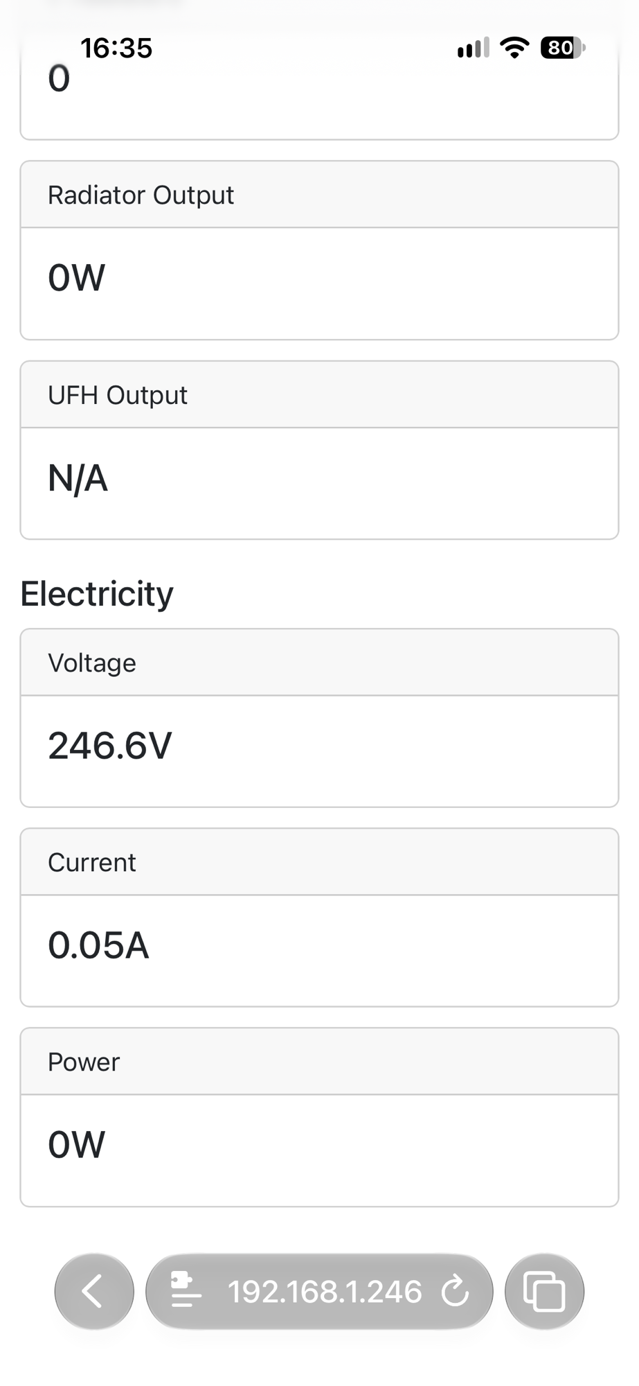
There is no power reading, since the heat pump is switched off at its isolator. Once it becomes fully operational, I hope to see some actual readings here!
All in all, I consider this a solid first test!
Antenna connectors are not all the same!
One thing I did discover during testing. The antenna connector on my C6-MINI-1U boards are different from the MinewSemi boards I use on my radiator sensors! U.FL vs W.FL. The espressif board uses more modern connectors, but I had no external antenna that would fit. The board does seem able to maintain a WiFi connection, so that’s good. Something to be aware of in future!
My board is designed in such a way that I can use the C6-MINI-1 module (integrated antenna), so it’s not a major problem (unlike my MBus board!)/
Next Steps
Now that my board is working (!), I need to think about the next steps.
The first thing is to fix the PCB traces. Otherwise, the board is in good shape. I keep seeing recommendations about putting some diodes across the USB connections for stability, but I’m not sure they are *absolutely* necessary.
This board is something I think other hobbyists would find useful. It’s an ESP32-C6, so it can do WiFi, Thread and Zigbee. It can be programming with ESPHome, ESP-IDF or Arduino (I think).
Would you be interested in buying one? Drop me a comment if you would and I can get a batch made up.
Did you enjoy this post?
If you found this blog post useful and want to say thanks, you’re welcome to buy me a coffee.
Be sure to check out my YouTube Channel too – https://youtube.com/tomasmcguinness
Thanks,
Tom!


Leave a comment