
In this post, we’re going to connect my ESP32 ModBus Adapter directly to my Solax X1 Inverter, so I can get real time data from it and expose it over Matter.
In a previous post, I exposed my SolaX over Matter by using ModBus TCP and that worked really well. However, I wanted to continue developing my ESP ModBus Adapter. The first one I connected had been working away for several weeks without any issue. It was connected to an SDM120M electricity meter, which was monitoring my new Kronoterm ASHP.
Since installing that board, I had revised the design to fixing a rather embarrassing issue in the layout (tracks going through a ground plane!). On receiving a new batch from PCB Way, I assembled them and moved onto the next ModBus device in my house: my Solax X1-G4 Inverter.
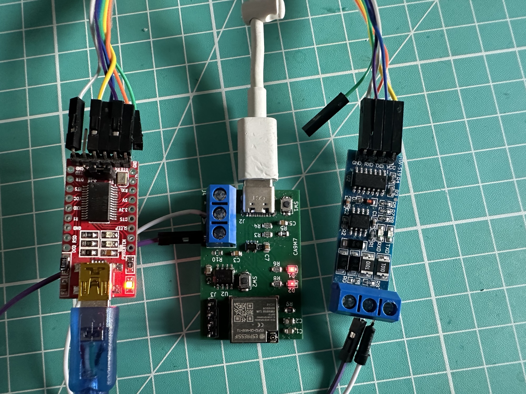
I wanted to continue the theme of using Matter and since I had written some ModBus TCP based firmware already, adapting that to Serial was straight forward.
Matter Support
The Matter Smart home protocol supports Solar Inverters using the Solar Power Device Type. It’s made up of several different devices, each one representing a part of the inverter, like a string of panels, or a battery.
A typical inverter might look like this, with 5 endpoints.
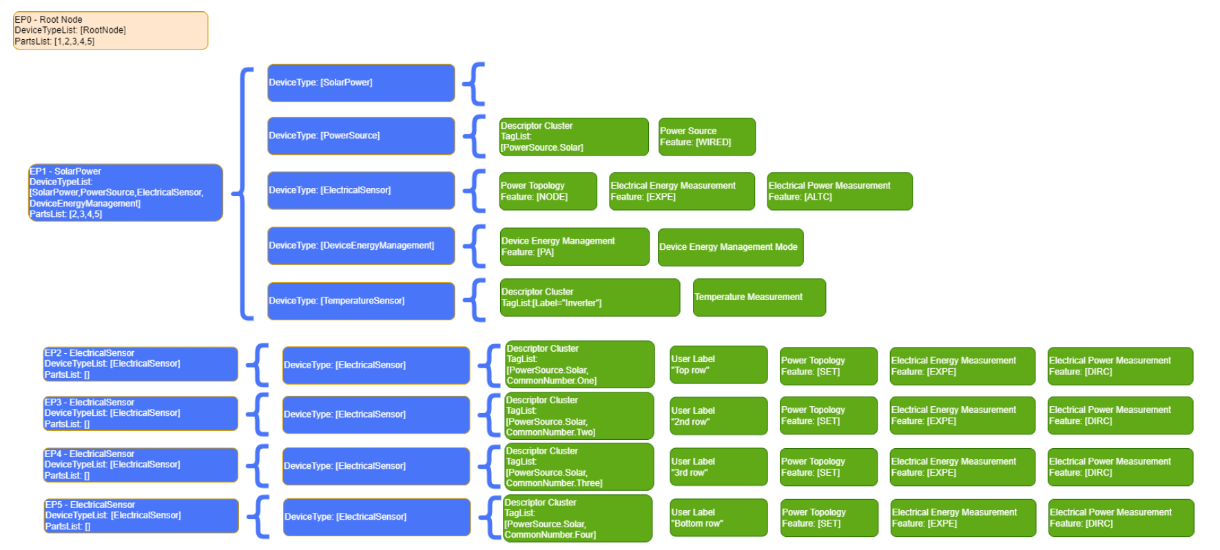
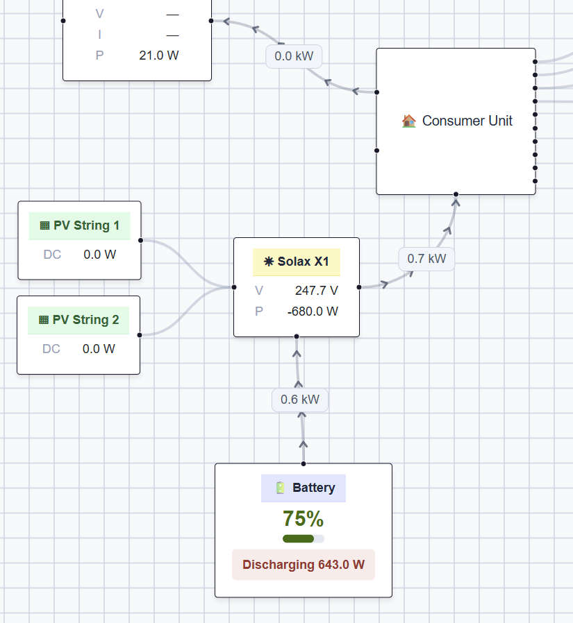
As I don’t have a full handle on Matter nor a full handle on my Inverter, I opted for least number of moving parts in my firmware. I added an Electrical Sensor for the inverter’s output, two electrical sensors for the PV strings and one Electrical Sensor for the battery. After commissioning my device with my Home Energy Manager, it rendered like this
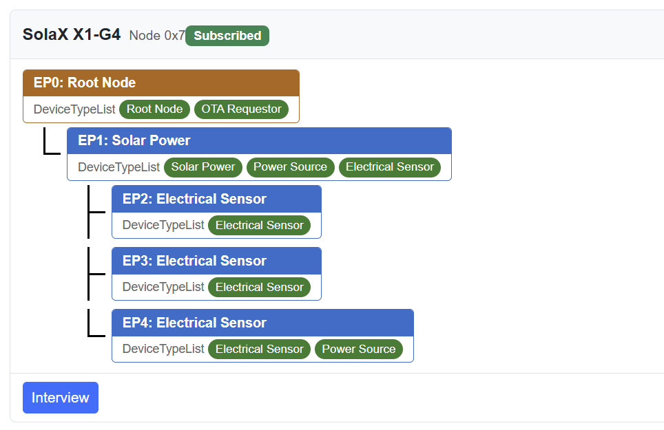
Far from meeting the specification, but enough to expose the data I needed.
Connecting it
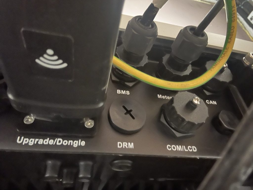
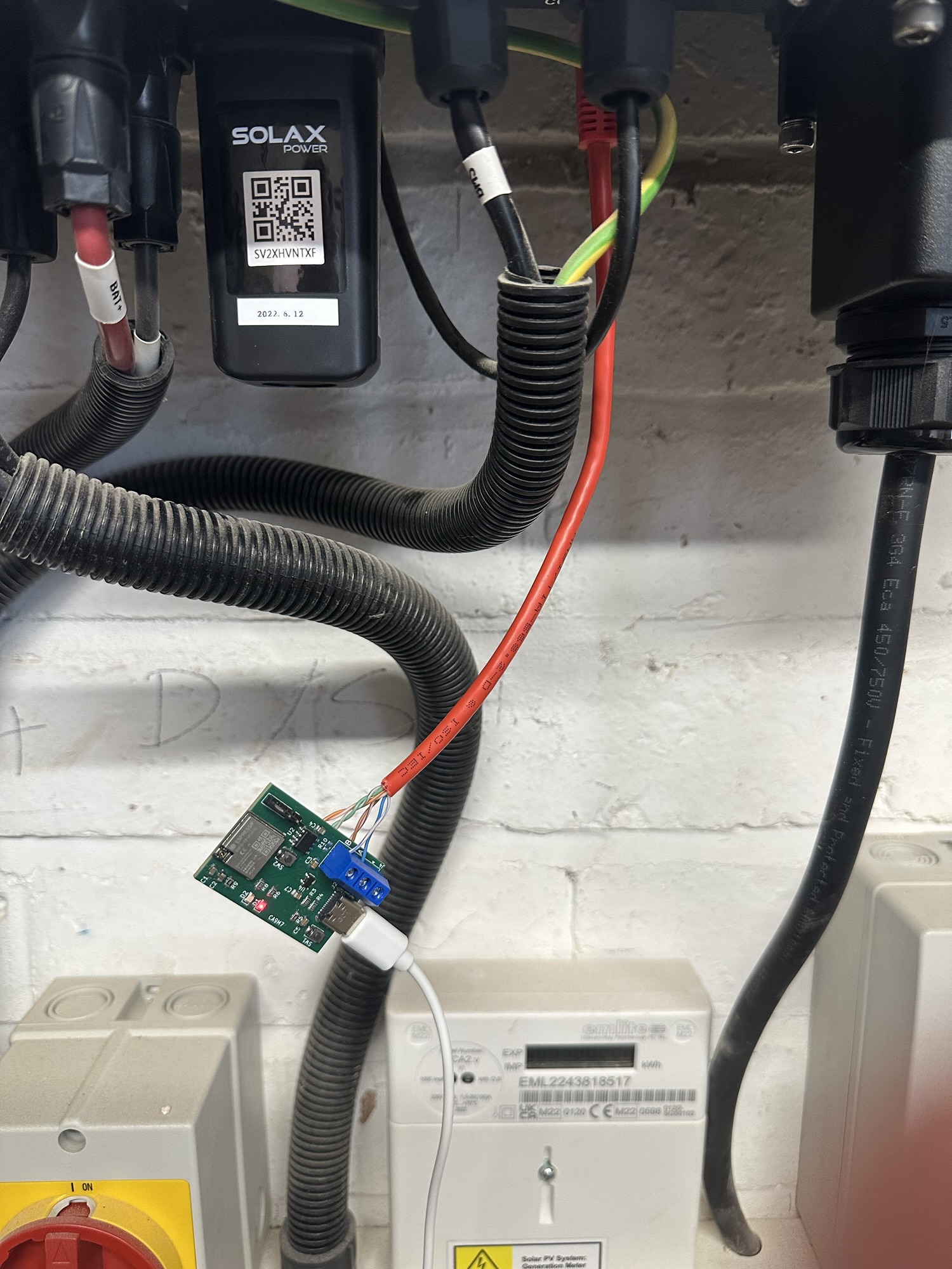
With the firmware written, the next step was connecting my adapter board to the inverter. To accomplish this, I needed to use the COM/LCD port on the bottom of the inverter itself.

Taking the cover off exposed an RJ45 port (ethernet connector).
From the inverter’s manual, it explained how to use this for ModBus
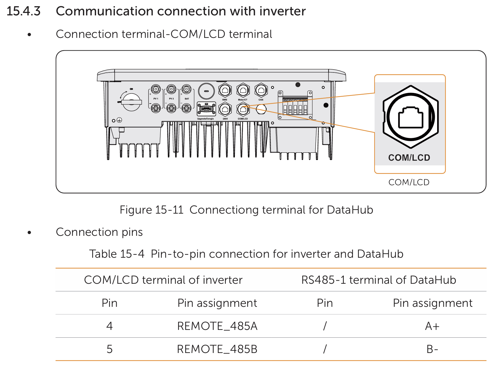
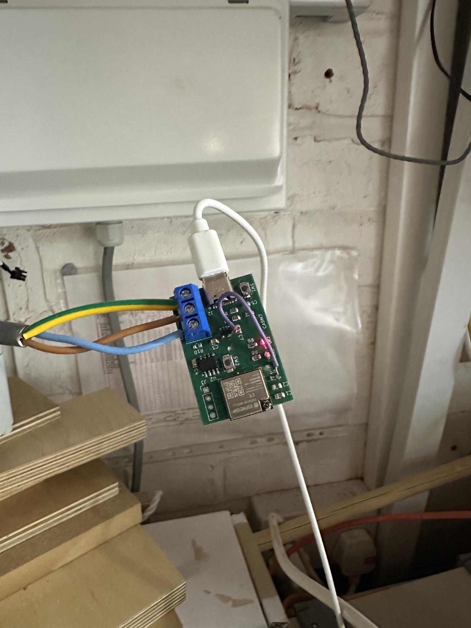
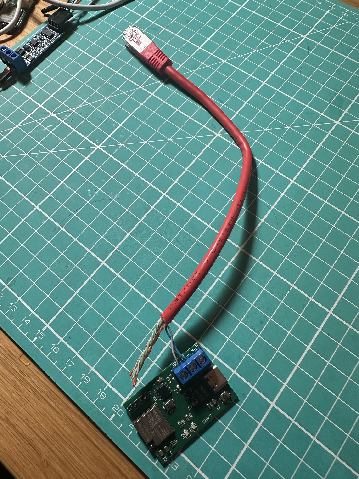
To make a connector, I just cut a patch cable in half. I then figured out that the blue wires (solid and striped) would be connected to pins 4 and 5. I connected them to the A & B ports of the adapter.
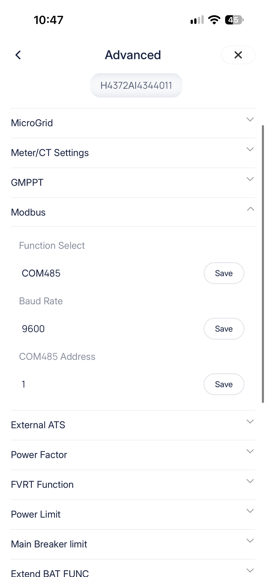
Before connecting it up, I entered the Inverter’s settings on the app and dropped the ModBus connection speed to 9600. Top tip – to access the Advanced settings from the app or inverter, you need to use the Admin password, which is different from the user password!
Finally, I psyched myself up, closed my eyes and plugged it in. Nothing went bang or burst into flames!
After a few seconds, I checked my Home Energy Manager and, to my pleasant surprise, I had real looking numbers! Honestly, I was shocked it worked first time.
Summary
So that’s it. I’ve exposed my Inverter over Matter. I could add this to a different Matter controller with just a Pairing Code. No faffing with IP addresses or integrations. It’s just plug and play.
I will hopefully expand this device over time. I would really love to understand how to leverage Matter’s Device Energy Management to control the inverter, especially the battery’s charging and discharging. For now, I’m happy to stay that my inverter is logging away.
If you want to try it yourself, all of the code, PCB designs and simulators are available on GitHub.
https://github.com/tomasmcguinness/esp32-modbus-serial-adapter
As it’s ESP32, you also don’t need to use Matter. You could write some ESPHome code or use Arduino too.
I’m considering selling my adapter board too, so if you’re interested, drop me a comment!
For now, it’s on to my next appliance – my Kronoterm Heat Pump!

Leave a comment