
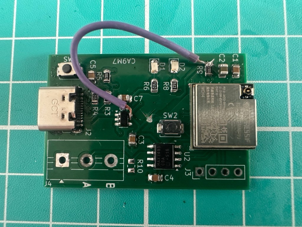
In addition to receiving my latest Dual Temperature Sensor boards from PCBWay, I also ordered a few of my Modbus ESP32 adapter boards. I was short a 210Ω resistor, but I soldered it all up anyway. Never hurts to practice. The first objective was getting the ESP32-C6 talking over USB so I could flash it.
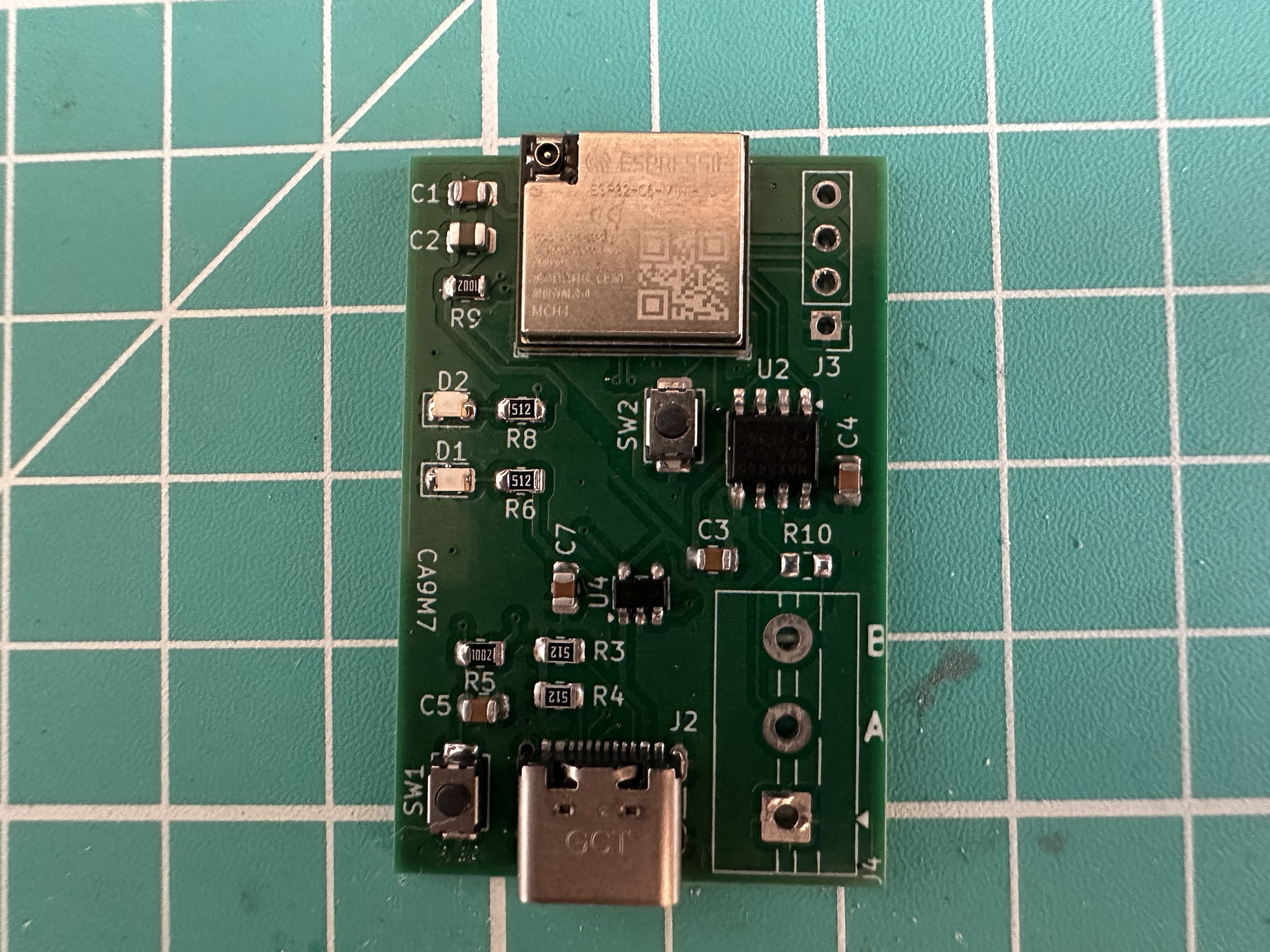
This time around, I tinned up the USB connector pads and the ESP32 pads before applying copious amounts of flux and popping it on the hot plate. The joints look really pretty good.
Powering up!
To power it up, I plugged it into some USB power. D1 is wired to light up on the arrival of 5V. Instead, Windows complained about a power surge!
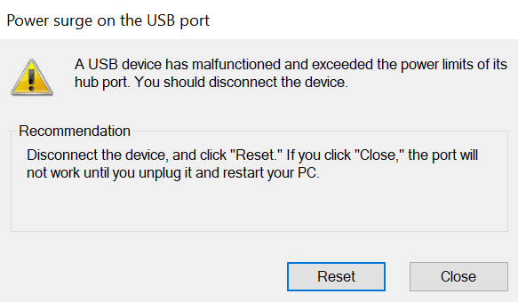
Not a good start! Not the worst start.
I began to do some continuity testing and to my surprise, the 5V and GND pins on the USB connector seemed to be shorted. I figured there must be a solder bridge beneath the connector, so I reflowed it. The short remained.
Claude suggested testing a board *without* any components and to my dismay, the short was present there too. After reviewing the PCB, I found the problem. I had a via from the top layer ground plane through to the 5V trace on the bottom plane 🤬🤬🤬
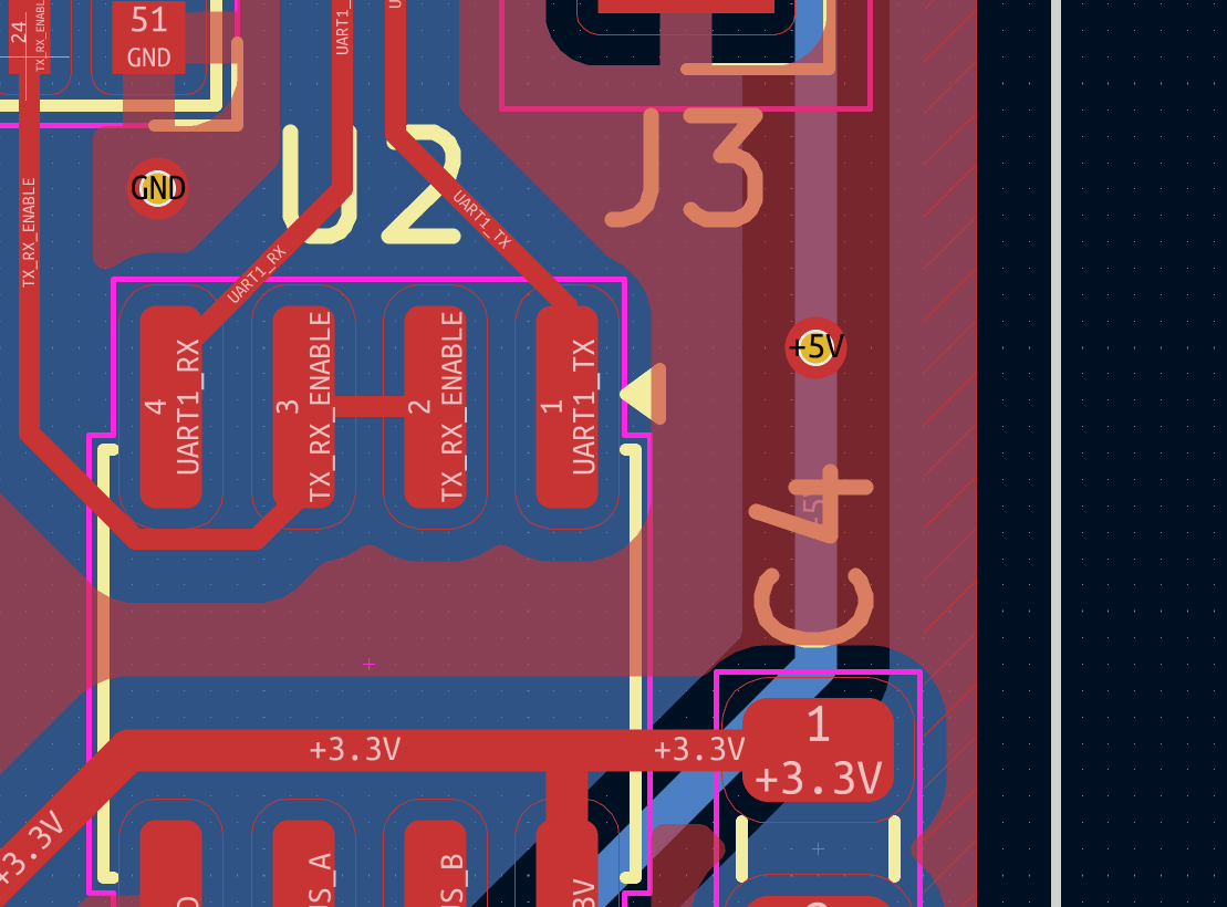
Not sure how I missed that. The KiCad DRC confirmed it. I guess I was in a rush to send the boards.
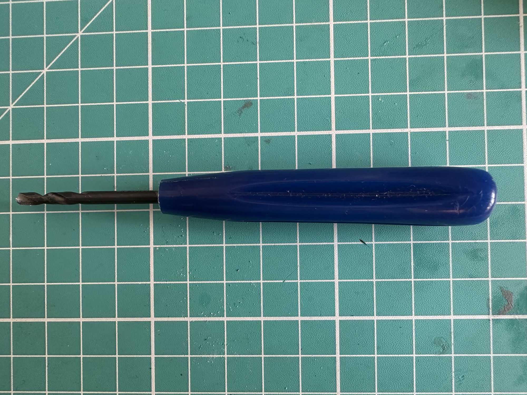
Thankfully, that 5V trace was only used by a diagnostic header. Using my little drill tool (for strip board), I drilled out the trace.
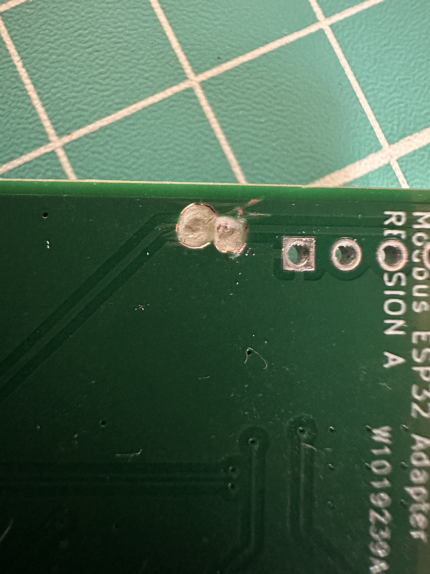
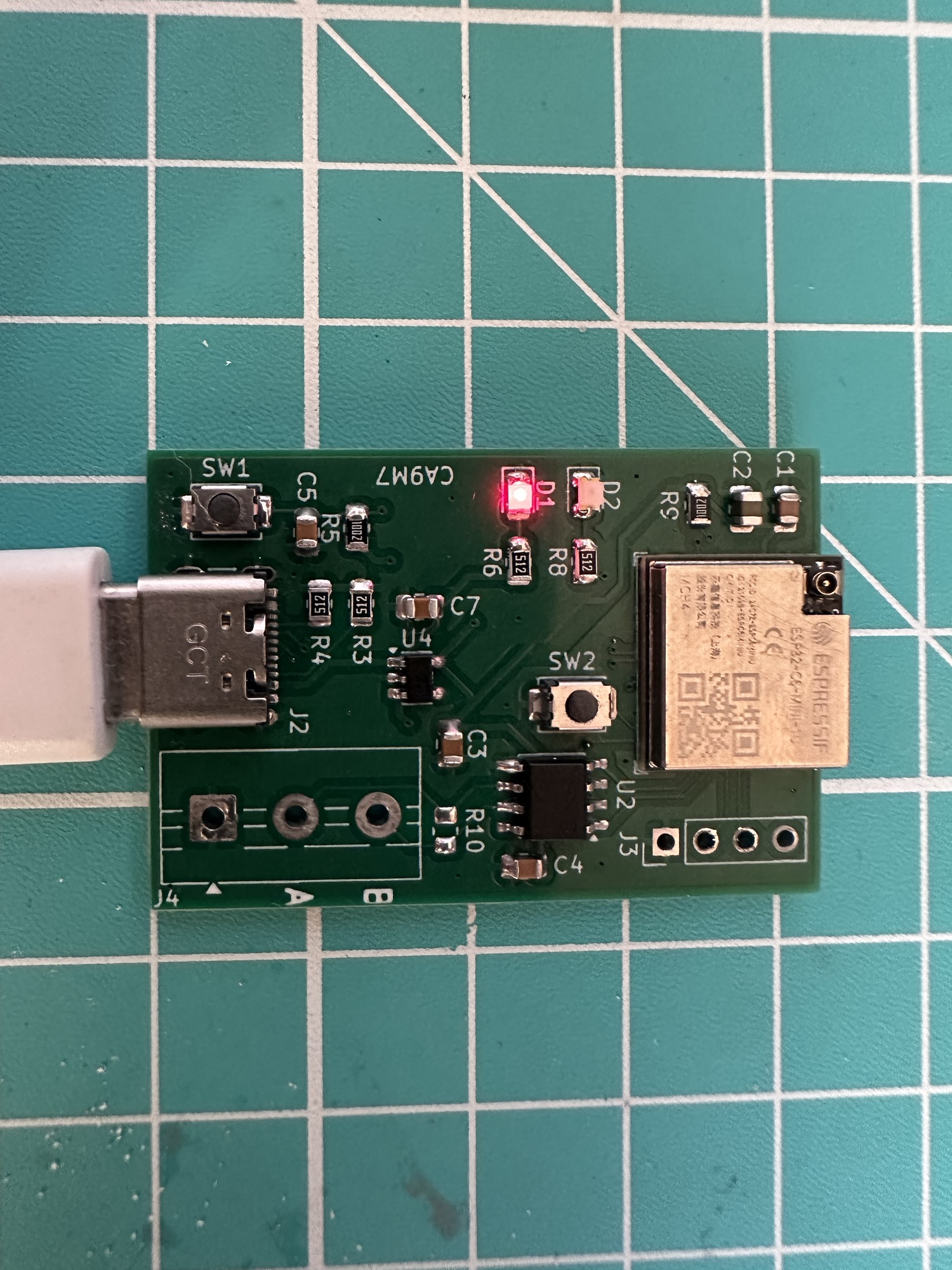
With the trace cut, the D1 LED lit up when I plugged in the device!
Where is my 3V?
I had 5V flowing in, but not USB device was being detected. I checked my ESP32 had power and discovered I had 0V on the LDO’s output. This is the first time I’ve tried the AP2112 LDO, so my initial thought was I messed up the pins.
On closer inspection, there was a short between VOUT and GND, which seemed strange. Obvious explanation was a solder bridge beneath the chip, so I warmed it up and removed the LDO.
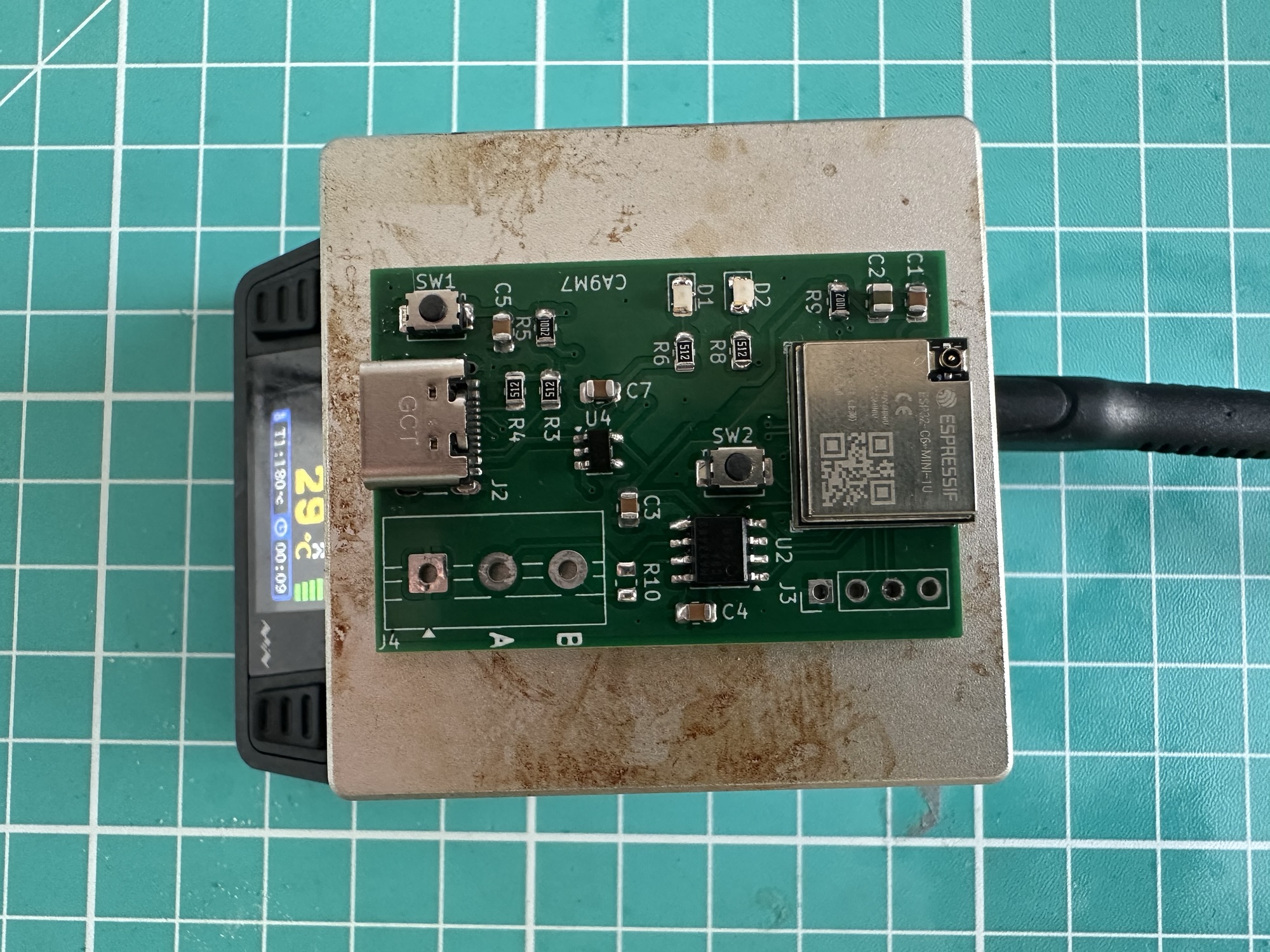
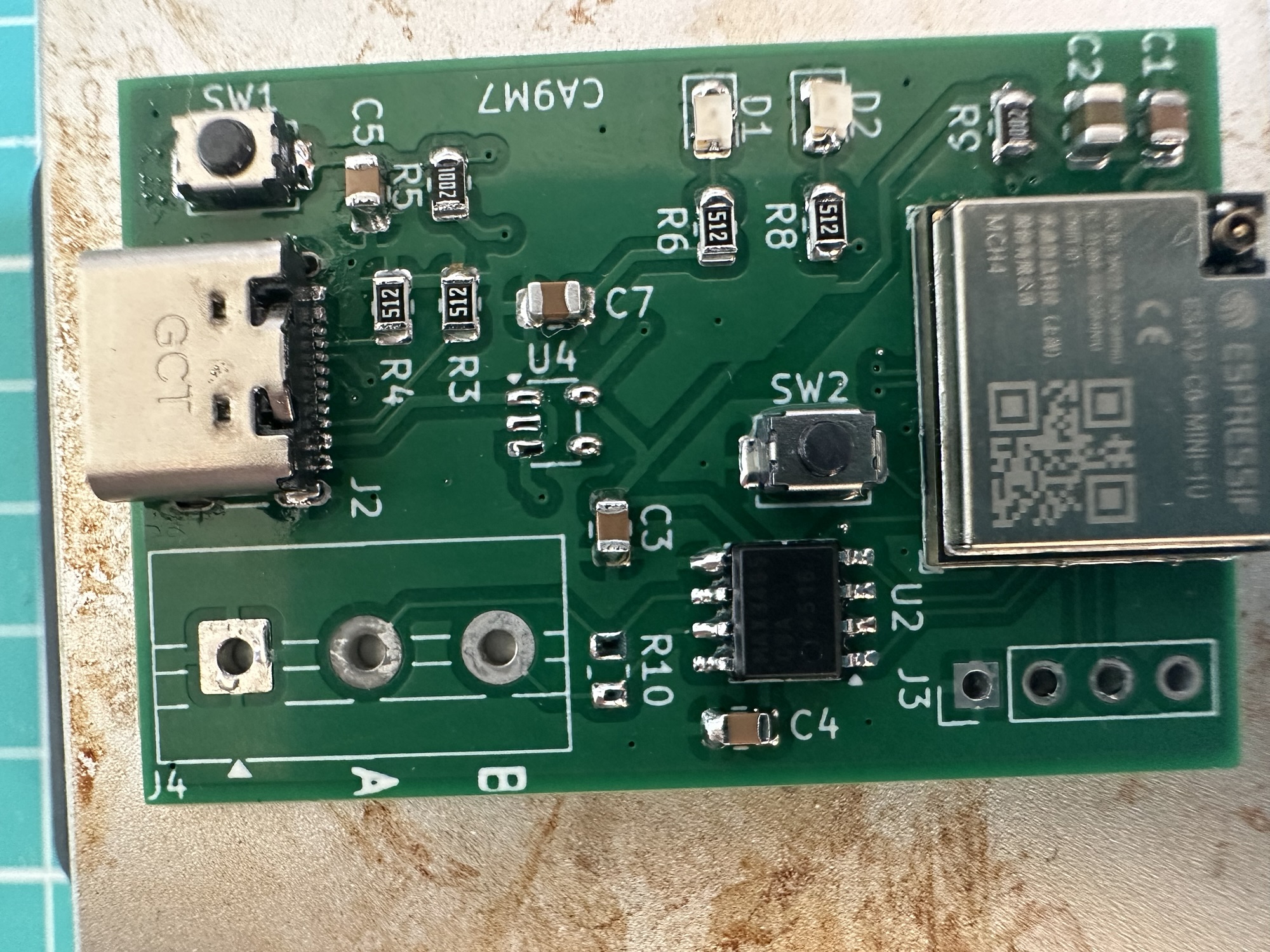
With no obvious solder bridge, perhaps my 5V to GND short fried the chip? As before, I checked on a bare board, and my heart sank when I found that was bridged too. That indicated a problem in the copper. After staring at my board for a few minutes, I found it.
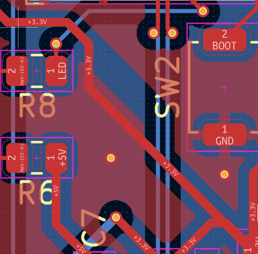
I clearly hadn’t updated the fill areas before sending the PCBWay. If I had updated them, the problematic 5V/GND via wouldn’t have been an issue.

I had no choice but to try and remove this short too.
“Forward, that is the battle-cry. Leave ideology to the arm-chair generals, it does me no good.” Frank Underwood
More “delicate” surgery
Using my drill tool, I broke the trace between the LDO and the GND plane
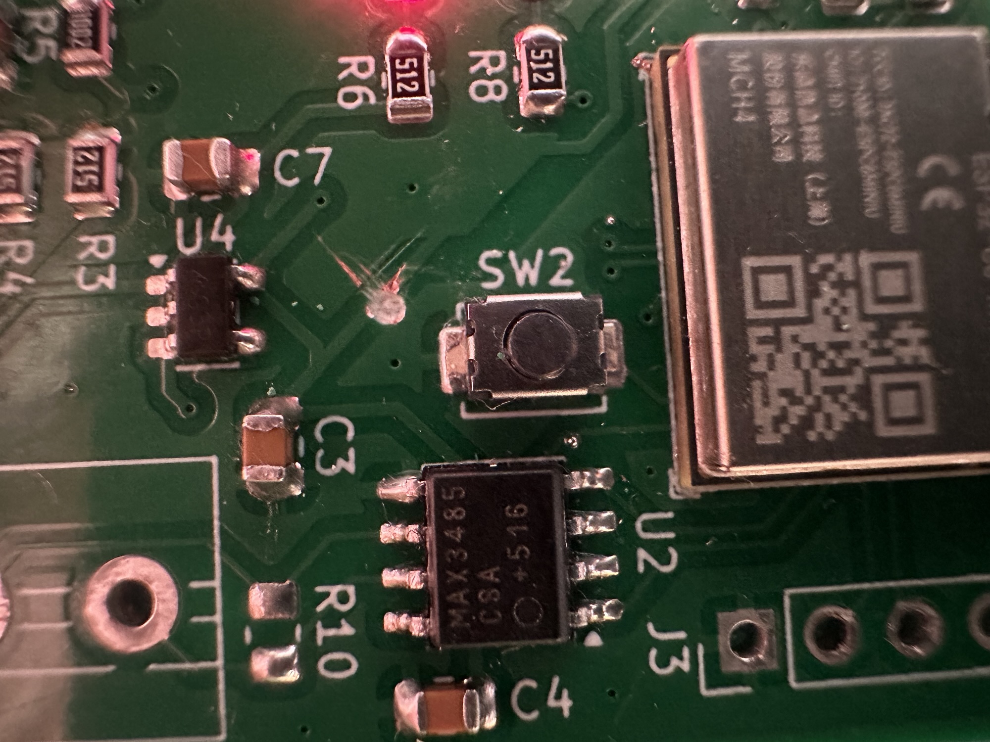
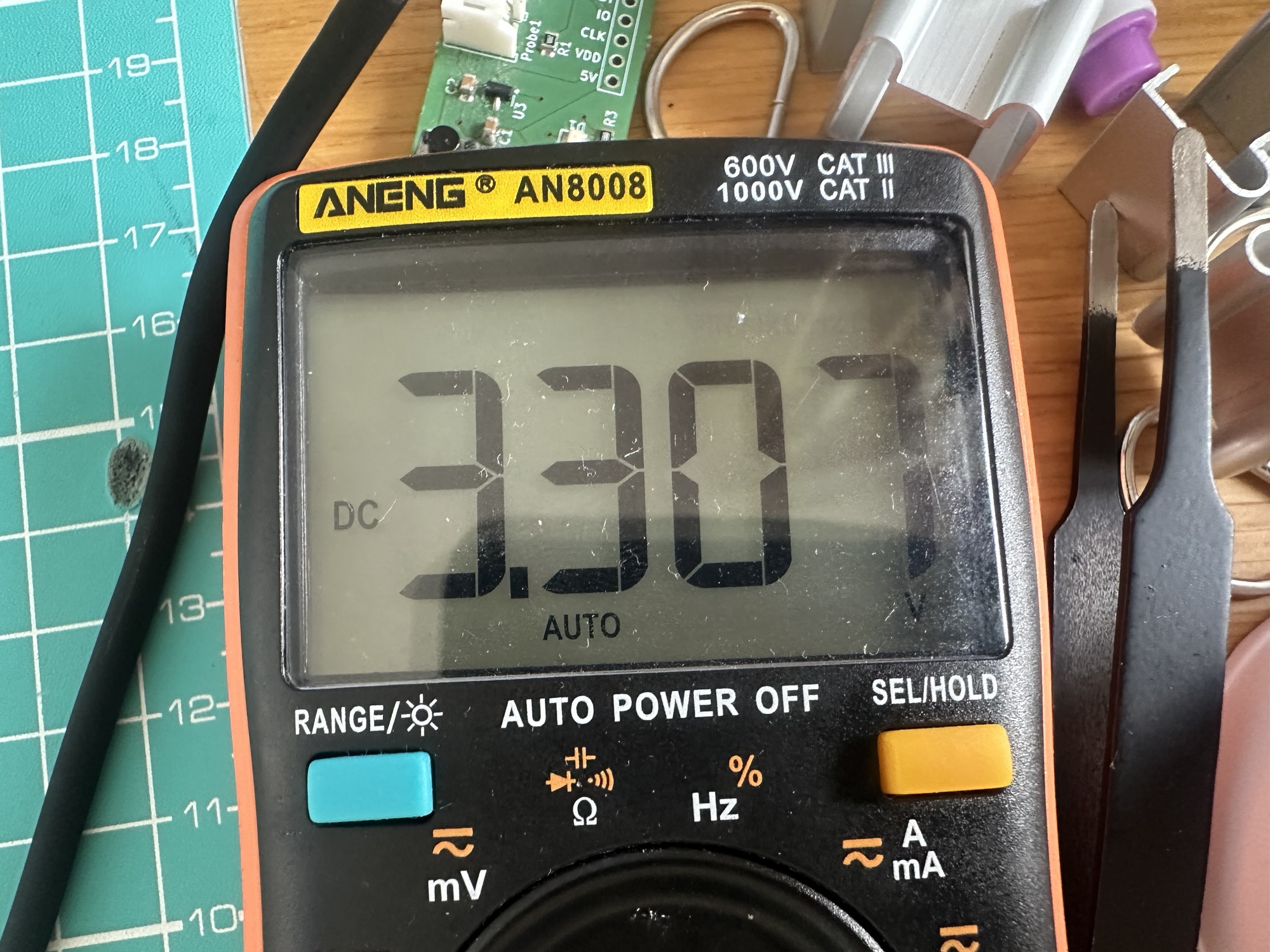
With the dead short removed, my LDO jumped into life, reporting 3.3V
Next, I needed to break the trace on the other side too, since R9 was also connected directly to the ground. This involved yet more delicate drill-based surgery 🤣
I confirmed the short was also remove and then put in a short piece of wire to reconnect power to the ESP32.
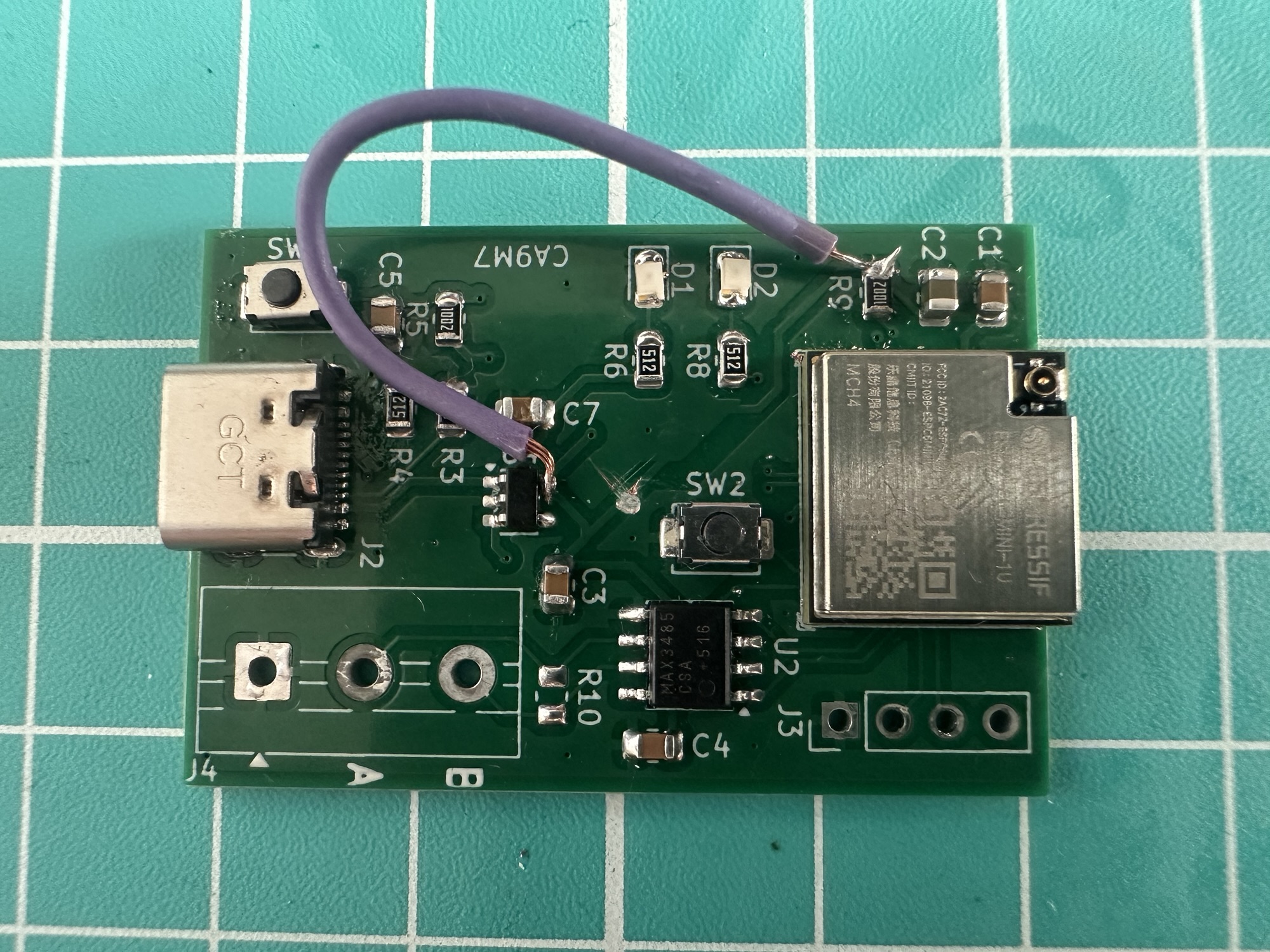
Holding down the BOOT button (SW2), I held my breath and re-connected the USB…
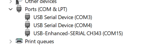
After a flicker or two, COM3 appeared, indicating my board was recognised! The last test was to ensure proper communication. For that, I used the esptool.py that comes with ESP-IDF. I ran it with the chip_id command
esptool.py chip_id
And just like that, it detected the ESP32-C6 chip!
Serial port /dev/ttyACM0Connecting...Detecting chip type... ESP32-C6Chip is ESP32-C6FH4 (QFN32) (revision v0.2)Features: Wi-Fi 6, BT 5 (LE), IEEE802.15.4, Single Core + LP Core, 160MHz, Embedded Flash 4MBCrystal is 40MHzUSB mode: USB-Serial/JTAGMAC: fc:01:2c:ff:fe:f3:ef:dcBASE MAC: fc:01:2c:f3:ef:dcMAC_EXT: ff:feUploading stub...Running stub...Stub running...Warning: ESP32-C6 has no Chip ID. Reading MAC instead.MAC: fc:01:2c:ff:fe:f3:ef:dcBASE MAC: fc:01:2c:f3:ef:dcMAC_EXT: ff:feHard resetting via RTS pin...
Amaze, Amaze!
Blink, Blink?
It wouldn’t be a complete test with running the blink sample. The LED is connected to GPIO14, so I updated the sample and flashed it
Summary
“A person who never made a mistake never tried anything new”
There were two mistakes in my layout, but to add insult to injury, both could have been avoided by refilling the ground planes! I’m not sure why I didn’t do that before sending it, but it’s something I’ll be checking from now on!
Regardless, I have a working board (at least the ESP32-C6 part). The new LDO is working as expected and I’m hoping to adopt this in other projects as it can supply 600mA, more than enough for the C6 & WiFi.
Next, I need to test the Modbus part.
If you don’t want to miss any of my posts, be sure to subscribe
Did you enjoy this post?
If you found this blog post useful and want to say thanks, you’re welcome to buy me a coffee.
Be sure to check out my YouTube Channel too – https://youtube.com/tomasmcguinness
Thanks,
Tom!


Leave a Reply