After all the excitement of getting the PCBs for my F.A.R.T. Sensor delivered, I discovered that I had made a mistake!
Let me show you what went wrong.
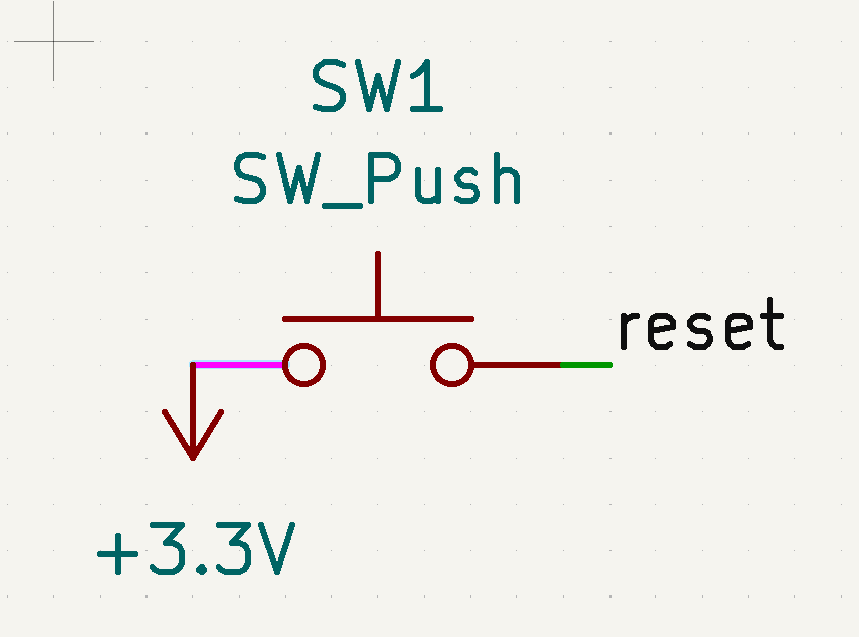
If you look at the top right, you’ll see SW1. These pads are for a small push switch, which will act as a “swap” button and reset button. The idea is that pushing the button sends power to one of the GPIOs.

I ended up connecting the wrong pins on the push button to my nRF52840!
What did I do wrong?
When designing my PCB in KiCAD , I popped a SW Push button onto the schematic and wired it up.
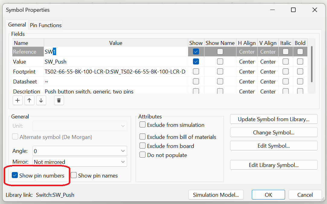
I then selected the TS02 as the footprint. This is the physical PCB layout for this schematic item. At this point it will be helpful to display the pin numbers, which can be turned on using KiCAD. Double clicking the symbol opens its properties. You can then turn on “Show pin numbers”
The schematic will now show that pin 1 went to 3.3V and pin 2 went to reset

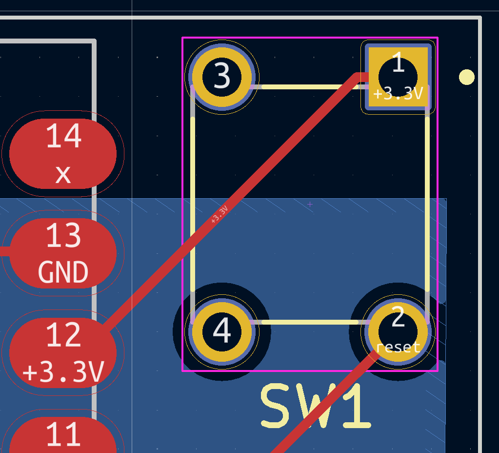
When the PCB was generated and I added the tracked, it looked like this. Pin 1 connected to 3.3V and pin 2 went off to the reset. Looked fine!
The Issue is uncovered!
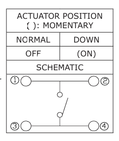
When I took delivery of some of the buttons from bitsbox.co.uk, I tested them with my multi-meter. I was saddened to find that pin 1 and pin 2 were permanently connected. Pin 3 and Pin 4 were the same!
Pushing the button would connect pair on the same side or the diagonally opposite pins. This meant my PCB wouldn’t work!
I opened up the datasheet for the TS02 switch and started reading. The pin numbers looked good when compared to the PCB, so it wasn’t that.
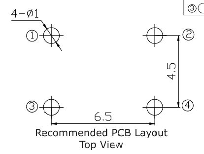
The problem lay in the *where* the switch actually was! D’oh! You can now see the problem.
Due to the way KiCAD works it just links by pin number. The schematic had two pins and the PCB had four pins. The footprint was one I installed from an outside source and I wondered if the solution was there too.
I couldn’t change the pin numbers, but perhaps there was a better schematic for the button?
The Fix
I went back to snapeda.com, where I originally downloaded the footprint for the TS02 button.
https://www.snapeda.com/parts/TS02-66-120-BK-160-LCR-D/Same%20Sky/view-part/
It actually did have the correct schematic. I just didn’t use it the first time around!

I deleted the existing switch from my schematic and added the TS02 one. Immediately, the pin numbers were better.

I wired it up to 3.3V and reset.

Upon updating the PCB from the schematic, the traces were now correct!!

Lessons
My main lesson here is to be more careful! The mistake was mine since I used the wrong schematic and didn’t pay attention to the pins! I’ll be more careful in future.
I’ve a few more tweaks to make to the board before I order another batch from aisler.net. I’ll be sure to update then!

Leave a reply to Zigbee F.A.R.T. PCB v0.2 – @tomasmcguinness Cancel reply