

This is a short update on the MBus ESP32 adapter I’m building. I wrote a long post about it over here, which I suggest you read first to give you some context.
When I designed the original circuit, I made two mistakes in the schematic. Each mistake impacted a different part of my circuit. In this post I want to talk about the Voltage Booster. In this part of the schematic, I put a critical junction at the wrong place, rendering the booster completely useless!
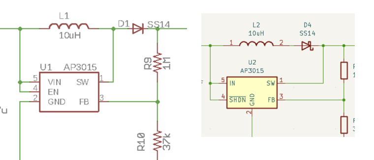
On my first revision, the SW pin of the AP3015 was in the wrong place. It should be before the diode (D4) and not after it. This meant the booster never had a chance to build up the voltage.
The voltage booster’s job is to convert 5V to 34V, the voltage needed for MBus communication. Without it, the MBus part doesn’t work. I corrected the schematic and updated the PCB before ordering new boards from PCBWay.
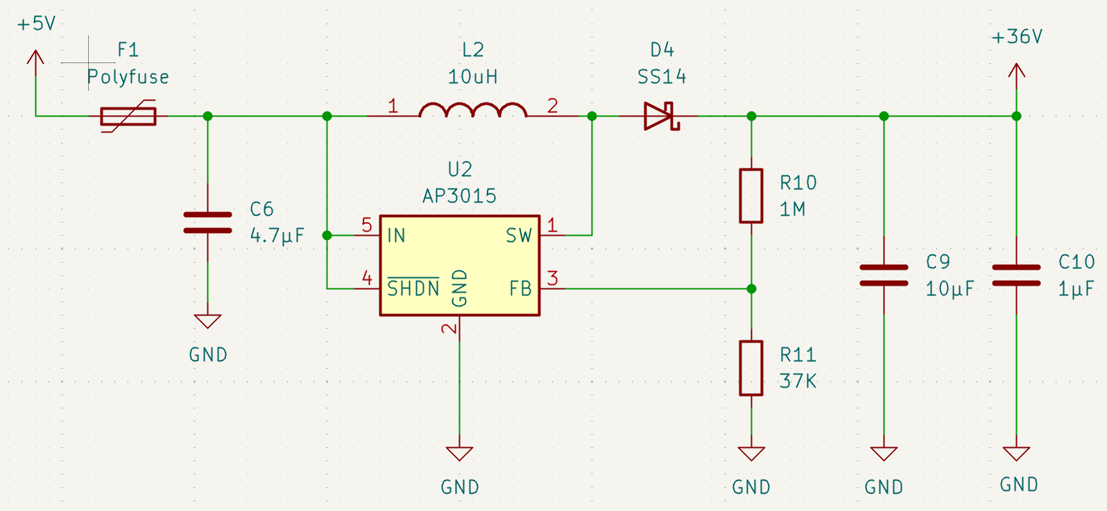
2nd Attempt
My updated boards (Revision F) arrived quickly from PCBWay. PCBWay very kindly paid for them to be manufactured and shipped. They even paid for the stencil, which was very kind! If you want a discount on your first order through PCBWay, please use this link – https://pcbway.com/g/a501i1
Through the Predictable Hardware Academy, I got lots of other bits of useful feedback, which I incorporated into my design.
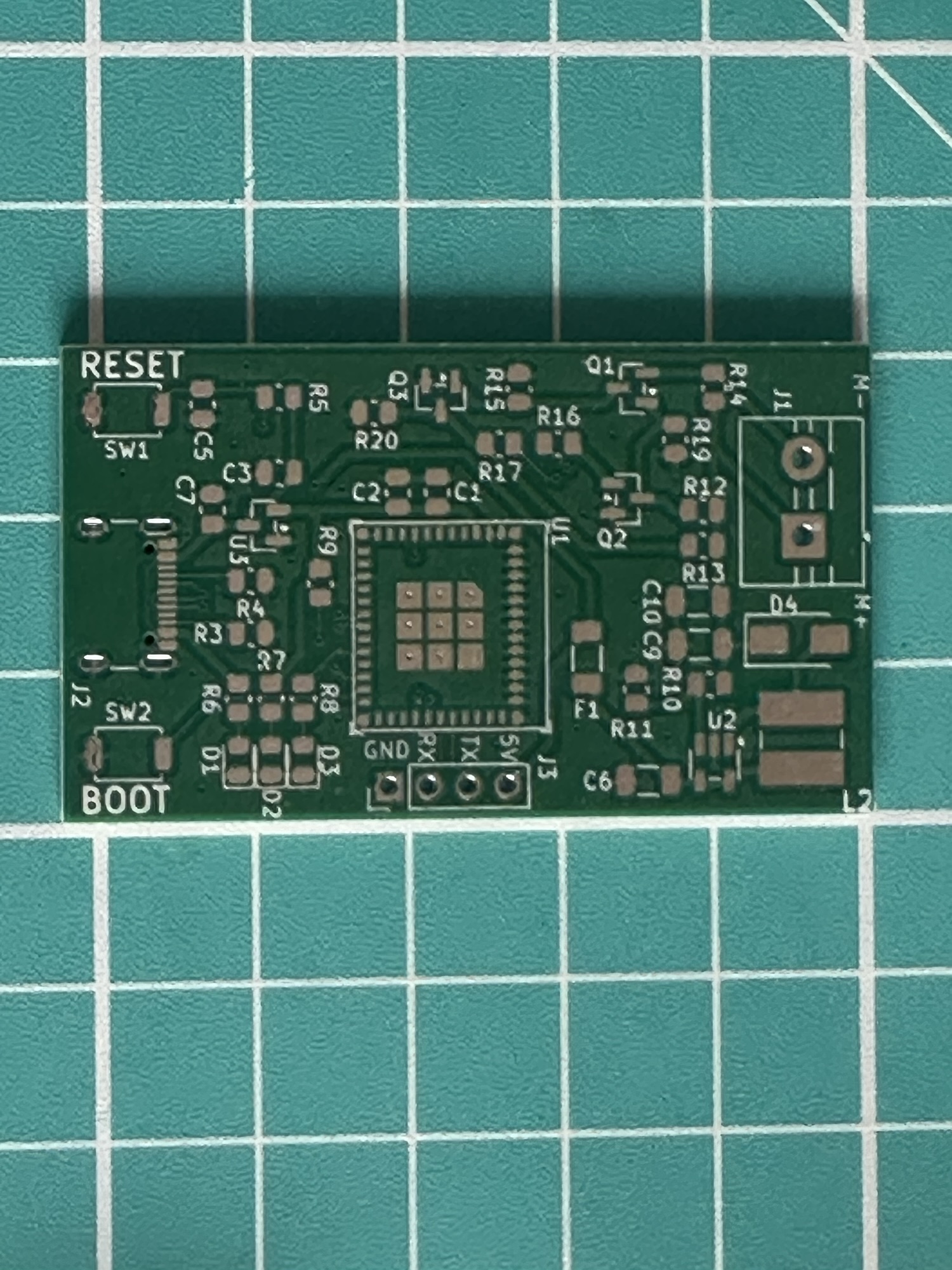
As I did with the first PCB, I added some of the parts, just so I could test the voltage booster. No point in adding the dozen ESP32 components if this part didn’t work!
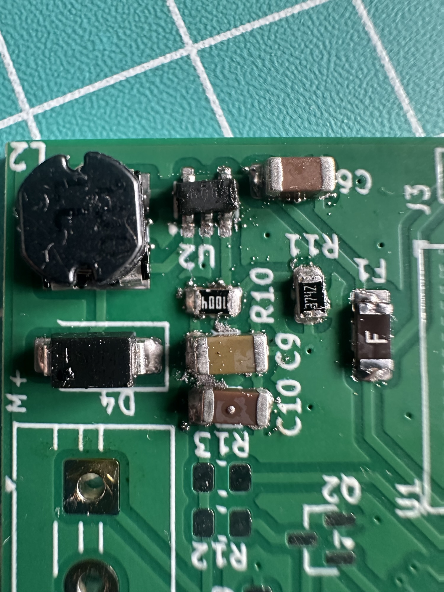
I powered it up from my bench supply and *nothing*. I was reading -1.1V at MBus+. Not the 34V I was hoping for.
Since I had a better understanding this time around, I checked the switch output of U2, the AP3015 booster. It flipped from 2.2V AC to 0V AC. This meant it was at least switching, which was good. Turning to Claude for advice, it immediately suggested my D4 diode was reversed. This explained the negative voltage.
Turned out that Claude was correct! Using my multi-meter, I checked the voltage drop and sure enough, the diode was the wrong way around. On much closer inspection (using my Phone’s camera), I noticed a little circular mark on the diode.
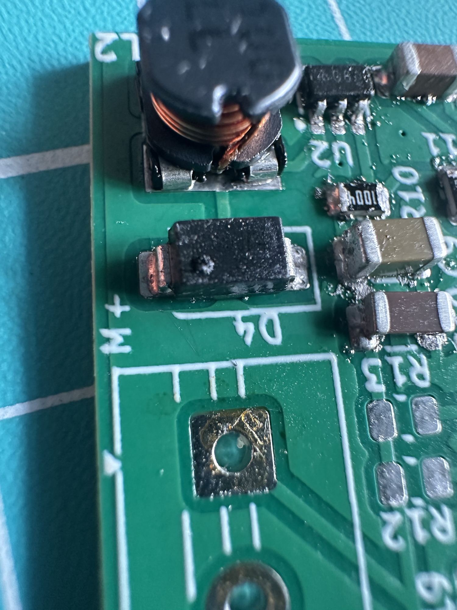
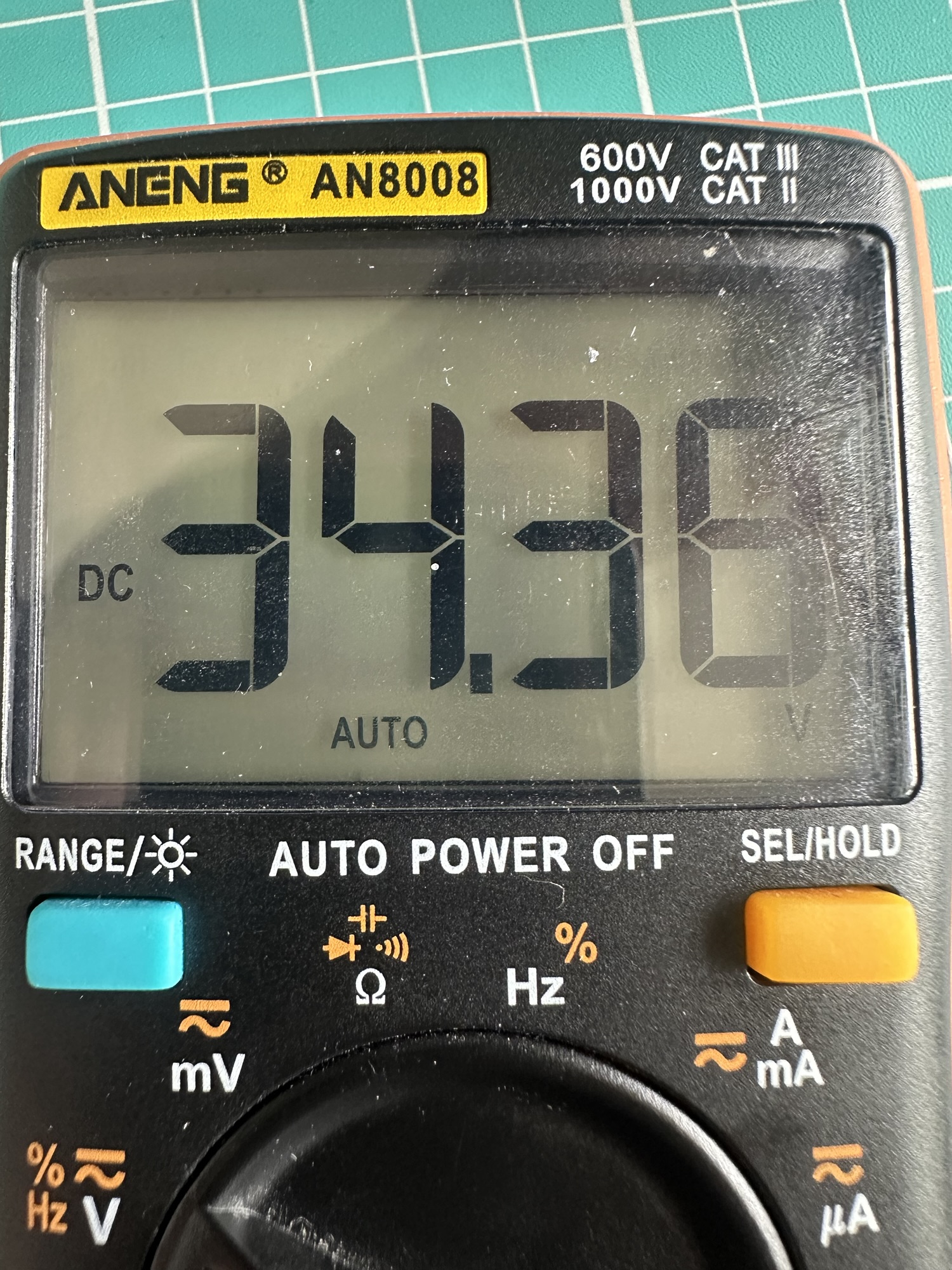
I flipped the diode 180° and tried the board again…this time my multi-meter showed what I hoped for – 34V!
Next Steps
With this part of the setup all working, the next thing I will look at is the UART level converters. In Revision A, I had one of the MOSFETS in the wrong orientation, which also rendered that part of the circuit non-functional!
If you want to follow along, be sure to subscribe
Did you enjoy this post?
If you found this blog post useful and want to say thanks, you’re welcome to buy me a coffee.
Be sure to check out my YouTube Channel too – https://youtube.com/tomasmcguinness
Thanks,
Tom!


Leave a comment